12 wiring checklist – Yaskawa J1000 Compact V/f Control Drive User Manual
Page 68
No.
Item
Page
13
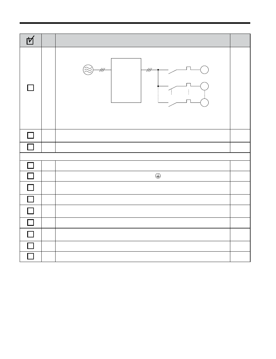
Set up overload protection circuits when running multiple motors from a single drive.
M1
OL1
OL2
OLn
MC1
MC2
MCn
M2
Mn
Drive
MC1 - MCn
OL 1 - OL n
... magnetic contactor
... thermal relay
Power supply
Note: Close MC1 through MCn before operating the drive.
-
14
If using a braking resistor or dynamic braking resistor unit, install a magnetic contactor.
Properly install the resistor, and ensure that overload protection shuts off the power supply.
15
Verify phase advancing capacitors are NOT installed on the output side of the drive.
-
Control circuit wiring
16
Use twisted-pair cables for all drive control circuit wiring.
17
Ground the shields of shielded wiring to the GND terminal.
18
If using a 3-Wire sequence, properly set parameters for multi-function contact input
terminals S1 through S5, and properly wire control circuits.
19
Check for any other wiring mistakes. Only use a multimeter to check wiring.
-
20
Properly fasten the control circuit terminal screws in the drive. Refer to
through
.
21
Pick up all wire clippings.
-
22
Ensure that no frayed wires on the terminal block are touching other terminals or
connections.
-
23
Properly separate control circuit wiring and main circuit wiring.
-
24
Analog signal line wiring should not exceed 50 m.
-
3.12 Wiring Checklist
68
YASKAWA ELECTRIC TOEP C710606 26D YASKAWA AC Drive – J1000 Quick Start Guide