B.2 parameter table – Yaskawa J1000 Compact V/f Control Drive User Manual
Page 237
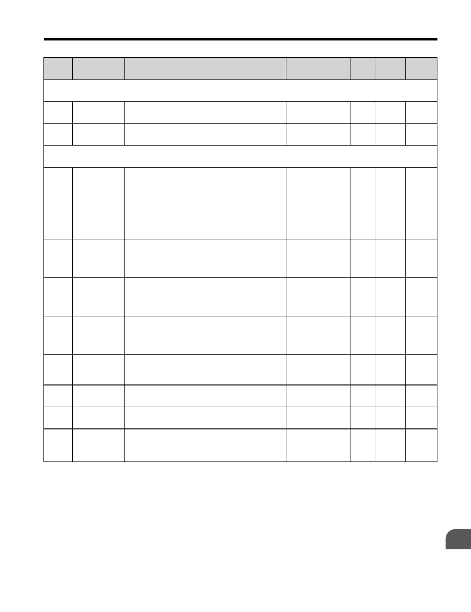
No.
Name
Description
Analog Output
Level
Unit Mode Addr.
Hex
U2: Fault History
Use U2 monitors to view fault history data.
U2-01 Current Fault Displays the current fault.
No signal output
avail.
–
O
80
U2-02 Previous
Fault
Displays the previous fault. o4-11 resets the
values for U2-02
No signal output
avail.
–
O
81
U4: Maintenance Monitors
Use U4 monitors to display drive maintenance information.
U4-01
<3>
Accumulated
Operation
Time
Displays the cumulative operation time of the
drive. The value for the cumulative operation
time counter can be reset in parameter o4-01.
Use parameter o4-02 to determine if the
operation time should start as soon as the power
is switched on or only while the run command
is present. The maximum number displayed is
99999, after which the value is reset to 0.
No signal output
avail.
1 h
O
4C
U4-04 Cooling Fan
Maintenance
Displays main cooling fan usage time as a
percentage of the expected performance life.
Parameter o4-03 can be used to reset this
monitor.
No signal output
avail.
1%
O
7E
U4-05
<2>
Capacitor
Maintenance
Displays main circuit capacitor usage time as a
percentage of the expected performance life.
Parameter o4-05 can be used to reset this
monitor.
No signal output
avail.
1%
O
7C
U4-06
<2>
Soft Charge
Bypass Relay
Maintenance
Displays the soft charge bypass relay
maintenance time as a percentage of the
estimated product life. Parameter o4-07 can be
used to reset this monitor.
No signal output
avail.
1%
O
7D6
U4-07
<2>
IGBT
Maintenance
Displays IGBT usage time as a percentage of
expected performance life. Parameter o4-09 can
be used to reset this monitor.
No signal output
avail.
1%
O
7D7
U4-08 Heatsink
Temperature
Displays the heatsink temperature.
10 V: 100 °C
1 °C
O
68
U4-09 LED Check
Lights all segments of the LED to verify that the
display is working properly.
No signal output
avail.
–
O
3C
U4-13 Peak Hold
Current
Displays the peak hold current during run.
No signal output
avail.
0.01
A
<1>
O
7CF
<1>
U1-03 and U4-13 display monitor contents in amp units. When reading the value of these monitors via
MEMOBUS/Modbus, a value of 8192 is equal to 100% of the drive rated output current.
<2>
When this value reaches 100%, the maintenance period has been reached for the component in question and the
drive is at risk of faulting out due to component failure. Periodically check the maintenance monitors to avoid
this situation.
<3>
MEMOBUS/Modbus communications data is in 10 h units. If data in 1 h units are also required, refer to register
0099H.
B.2 Parameter Table
YASKAWA ELECTRIC TOEP C710606 26D YASKAWA AC Drive – J1000 Quick Start Guide
237
B
Parameter List