Installing fuses on the input side, Attachment for external heatsink, Noise filter installation – Yaskawa J1000 Compact V/f Control Drive User Manual
Page 191: Output
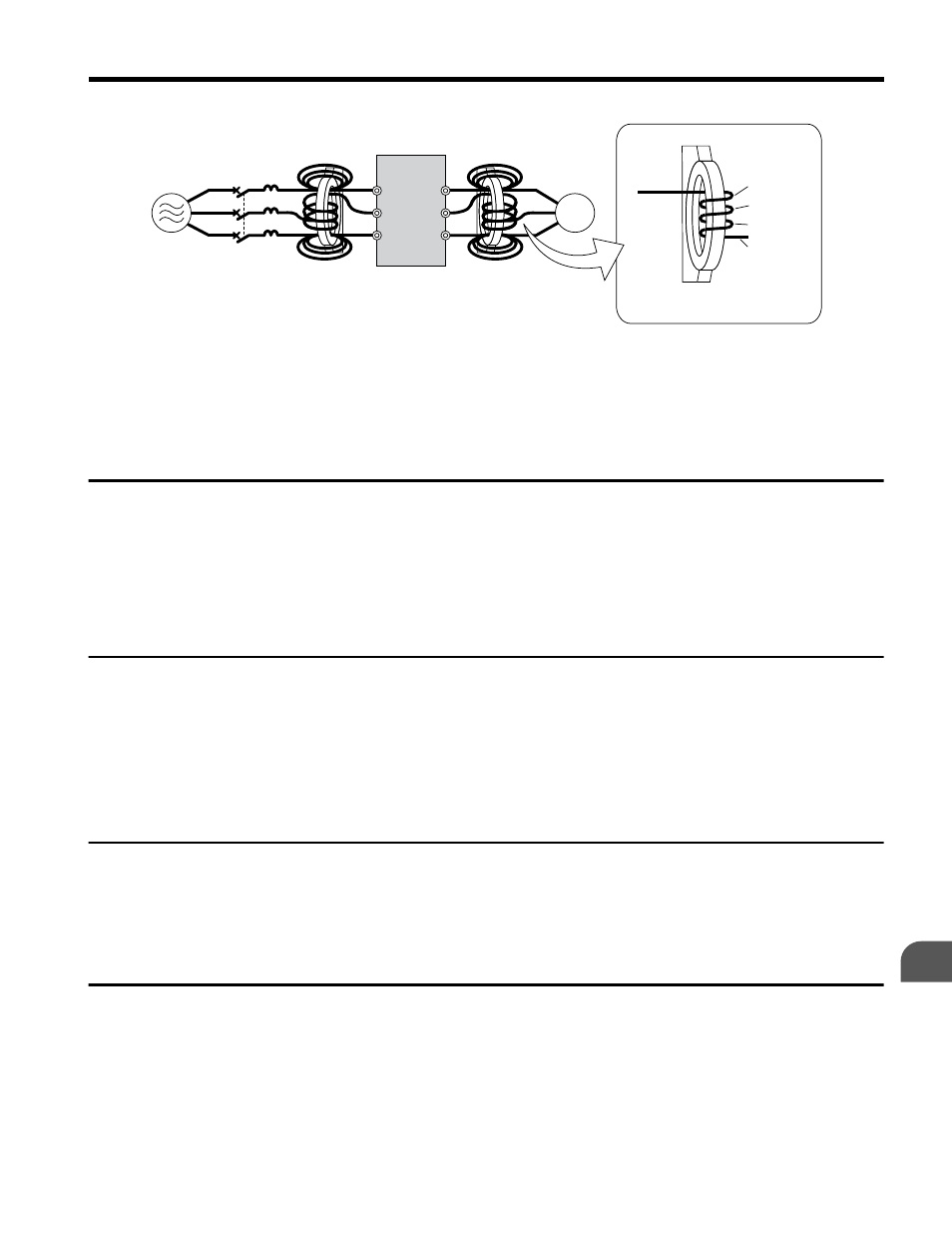
Close-up of V/T2-phase wiring
1st pass
4th pass
3rd pass
2nd pass
D
E
F
C
B
A
Pass each wire (U/T1, V/T2, W/T3)
through the core 4 times.
R/L1
S/L2
T/L3
U/T1
V/T2
W/T3
A – Power supply
B – MCCB
C – Zero-phase reactor on
input side
D – Drive
E – Zero-phase reactor on
output side
F – Motor
Figure 7.10 Zero-Phase Reactor
u
Installing Fuses on the Input Side
Always install input fuses to the input side of the as a protective measure against damage
caused by a short circuit.
Refer to Factory Recommended Drive Branch Circuit Protection on page 258
for details
on input fuse selection.
u
Attachment for External Heatsink
An external attachment can be used to project the heatsink outside of an enclosure to ensure
that there is sufficient air circulation around the heatsink. This installation method still requires
a certain amount of airflow over the drive case.
Refer to Output Current Derating Due to
Ambient Temperature on page 211
if derating is required. Contact a Yaskawa sales
representative for more information.
u
Noise Filter Installation
This drive has undergone testing in conformance with IEC/EN 61800-5-1 and is in compliance
Refer to EMC Guidelines Compliance on page 248
information on selecting a noise filter.
u
Installing a Motor Thermal Overload (oL) Relay on the Drive
Output
Motor thermal overload relays protect the motor by disconnecting power lines to the motor
due to a motor overload condition.
Install a motor thermal overload relay between the drive and motor:
7.4 Installing Peripheral Devices
YASKAWA ELECTRIC TOEP C710606 26D YASKAWA AC Drive – J1000 Quick Start Guide
191
7
Peripheral Devices & Options