Motor protection: l1-01 and l1-02, Electronic thermal motor protection – Yaskawa J1000 Compact V/f Control Drive User Manual
Page 107
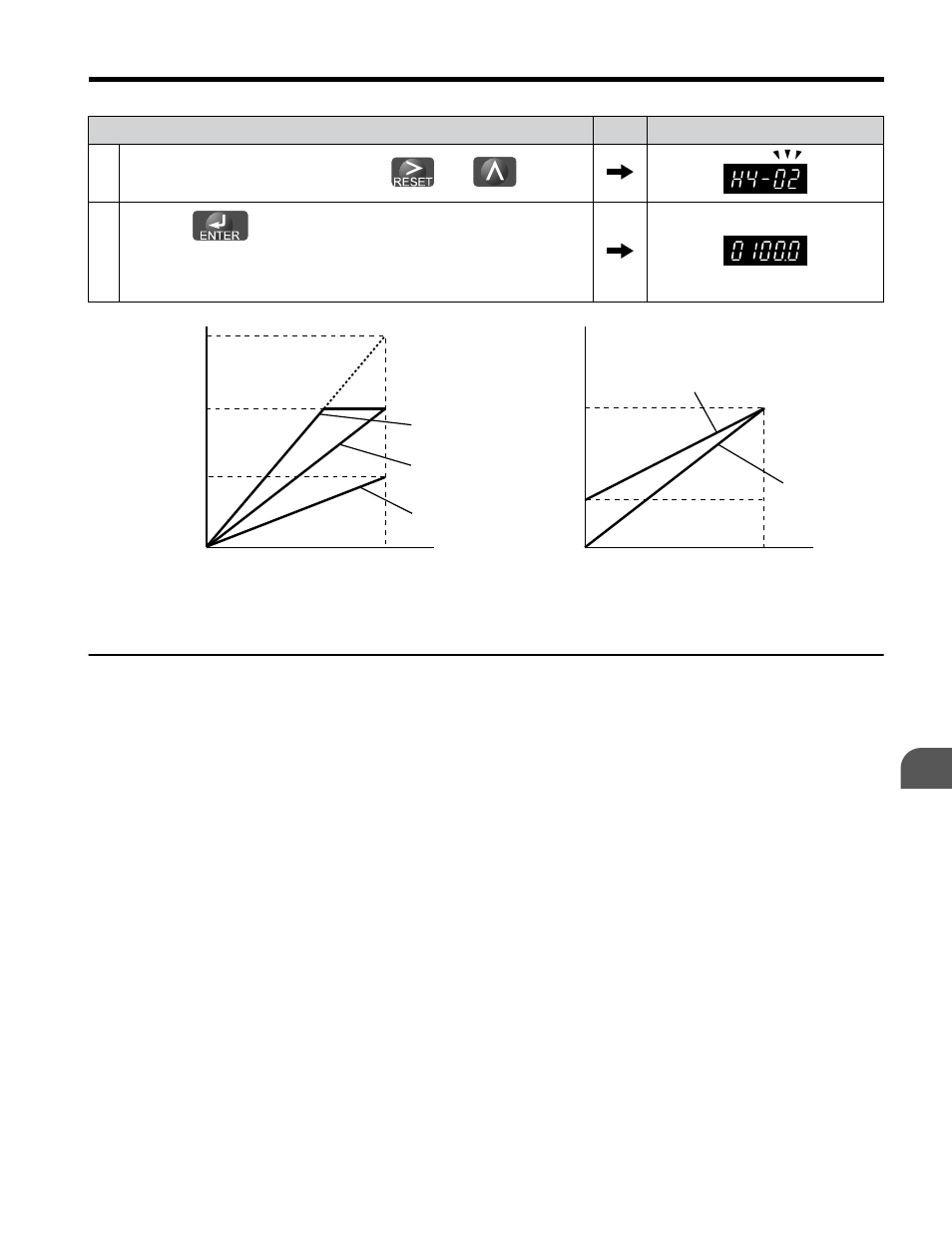
Step
Display/Result
1.
Select H4-02 or H4-03 by pressing the
and
keys.
2.
Press the
key while the drive is stopped and the following
voltage is output for adjustment:
Output voltage = (10 V x Output Gain (H4-02) + Output Bias (H4-03).
Using this output, adjust output gain (H4-02) and output bias (H4-03).
0 V
3 V
10 V
Bias 30%
Gain 100%
Bias 0%
Gain 100%
100%
Monitor value
0%
Gain 50%
Bias 0%
Terminal AM
output
voltage
0 V
5 V
10 V
Gain 150%
Bias 0%
Gain 100%
Bias 0%
100%
Monitor value
0%
Terminal AM
output
voltage
Figure 4.18 Analog Output Gain/Bias Setting
u
Motor Protection: L1-01 and L1-02
This section explains how to set motor overload protection.
n
Electronic Thermal Motor Protection
The drive has built-in electronic thermal overload protection to detect overload conditions.
This protection meets standards set by UL and cUL for motor thermal overload protection.
The protective feature is activated when the output current rises above the motor rated current
for a specified time. This speed sensitive protective feature interrupts the motor current to
protect the motor wiring and windings in the event of overload, eliminating the need for an
external overload device. When multiple motors are used with a single drive, separate overload
devices are required to properly protect the individual motor branches.
4.5 Basic Operation
YASKAWA ELECTRIC TOEP C710606 26D YASKAWA AC Drive – J1000 Quick Start Guide
107
4
Start-Up Programming & Operation