4 fault detection – Yaskawa J1000 Compact V/f Control Drive User Manual
Page 137
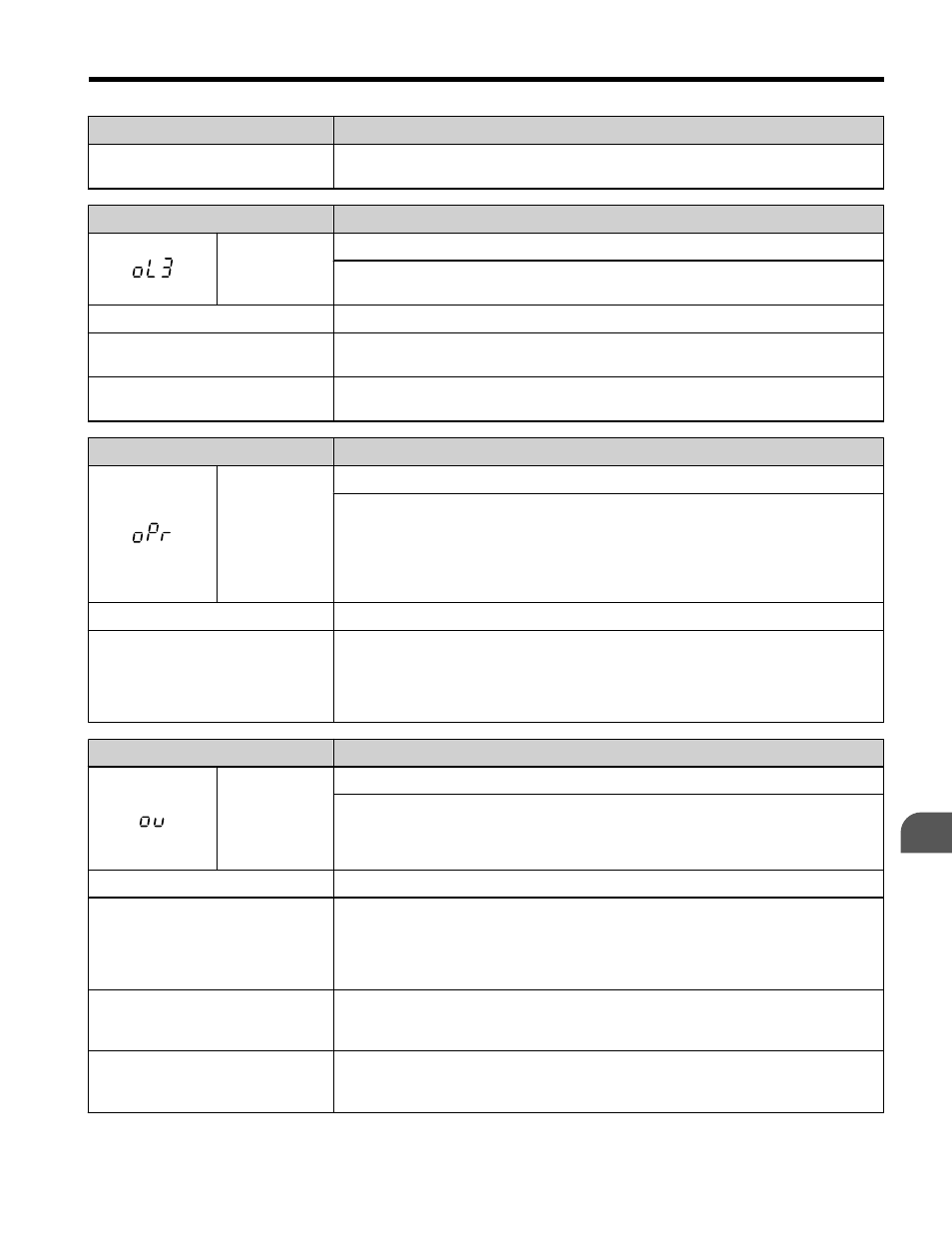
Digital Operator Display
Fault Name
Output current fluctuation due to
input phase loss
Check the power supply for phase loss.
Digital Operator Display
Fault Name
oL3
Overtorque Detection 1
The current has exceeded the value set for torque detection (L6-02) for longer
than the allowable time (L6-03).
Cause
Possible Solution
Parameter settings are not
appropriate for the type of load.
Check the settings of parameters L6-02 and L6-03.
There is a fault on the machine side
(e.g., the machine is locked up).
Check the status of the load. Remove the cause of the fault.
Digital Operator Display
Fault Name
oPr
External Digital Operator Connection Fault
• The external operator has been disconnected from the drive.
Note: An oPr fault will occur when all of the following conditions are true:
• Output is interrupted when the operator is disconnected (o2-06 = 1).
• The run command is assigned to the operator
(b1-02 = 0 and LOCAL has been selected).
Cause
Possible Solution
External operator is not properly
connected to the drive.
• Check the connection between the operator and the drive.
• Replace the cable if damaged.
• Turn off the drive input power and disconnect the operator. Next reconnect the
operator and turn the drive input power back on.
Digital Operator Display
Fault Name
ov
Overvoltage
Voltage in the DC bus has exceeded the overvoltage detection level.
• For 200 V class: approximately 410 V
• For 400 V class: approximately 820 V (740 V when E1-01 is less than 400)
Cause
Possible Solution
Deceleration time is too short and
regenerative energy flows from the
motor into the drive.
• Increase the deceleration time (C1-02, C1-04).
• Install a braking resistor or a dynamic braking resistor unit.
• Set L3-04 to 1 to enable stall prevention during deceleration.
Stall prevention is enabled as the default setting.
Excessive braking load.
The braking torque was too high, causing regenerative energy to charge the DC
bus.
Reduce the braking torque, use a braking option, or lengthen decel time.
Surge voltage entering from the
drive input power.
Install a DC link choke.
Note: Voltage surge can result from thyristor convertor and phase advancing
capacitor using same drive main input power supply.
5.4 Fault Detection
YASKAWA ELECTRIC TOEP C710606 26D YASKAWA AC Drive – J1000 Quick Start Guide
137
5
Troubleshooting