Control circuit terminal block functions, Input terminals – Yaskawa J1000 Compact V/f Control Drive User Manual
Page 53
<3> Minimum load: 5 Vdc, 10 mA (reference value).
u
Control Circuit Terminal Block Functions
Drive parameters determine which functions apply to the multi-function digital inputs (S1 to
S5), multi-function digital outputs (MA, MB, MC), and multi-function analog output (AM).
The default is called out next to each terminal in
.
WARNING! Sudden Movement Hazard. Always check the operation and wiring of control circuits after being
wired. Operating a drive with untested control circuits could result in death or serious injury.
WARNING! Confirm the drive I/O signals and external sequence before starting test run. Failure to comply
may result in death or serious injury.
n
Input Terminals
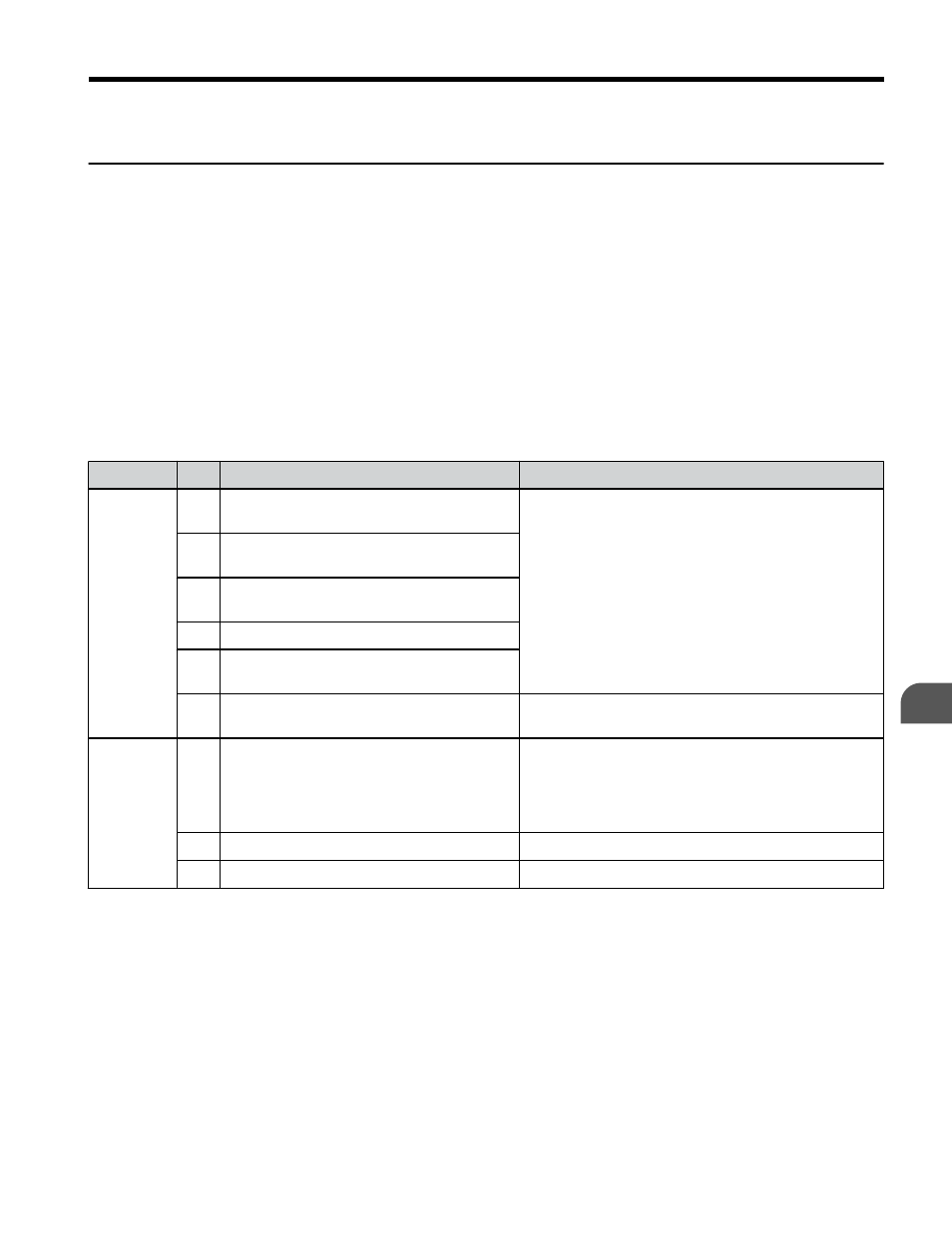
Table 3.6 Control Circuit Input Terminals
Type
No.
Terminal Name (Function)
Function (Signal Level) Default Setting
Multi-
Function
Digital
Inputs
S1 Multi-function input 1 (Closed: Forward
run, Open: Stop)
24 Vdc, 8 mA
Note: Drive preset to sinking mode. When using
source mode, set DIP switch S3 to allow for a 24 Vdc
Sourcing Mode Switch on page 59
S2 Multi-function input 2 (Closed: Reverse
run, Open: Stop)
S3 Multi-function input 3 (External fault
(N.O.)
S4 Multi-function input 4 (Fault reset)
S5 Multi-function input 5 (Multi-step speed
reference 1)
SC Multi-function input common (Control
common)
Sequence common
Main
Frequency
Reference
Input
A1 Frequency reference
Input voltage or input current (Selected by DIP switch
S1 and H3-01) 0 to +10 Vdc (20 kΩ),
Resolution: 1/1000
4 to 20 mA (250 Ω) or 0 to 20 mA (250 Ω),
Resolution: 1/500
+V Analog input power supply
+10.5 Vdc (max allowable current 20 mA)
AC Frequency reference common
0 Vdc
3.7 Control Circuit Wiring
YASKAWA ELECTRIC TOEP C710606 26D YASKAWA AC Drive – J1000 Quick Start Guide
53
3
Electrical Installation