7 control circuit wiring, Control circuit wiring, J1000 – Yaskawa J1000 Compact V/f Control Drive User Manual
Page 52
3.7
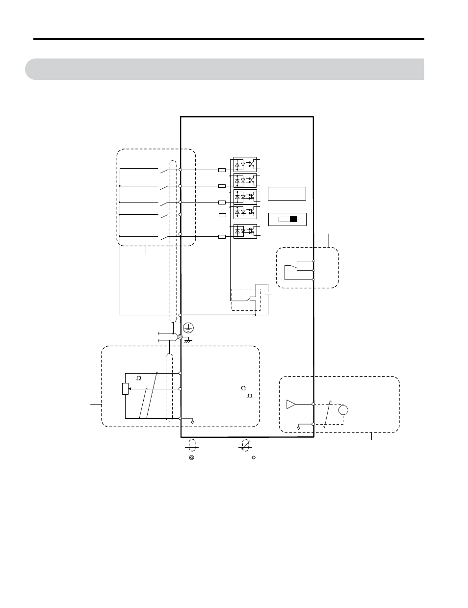
Control Circuit Wiring
NOTICE: Do not solder the ends of wire connections to the drive. Soldered wire connections can loosen over
time. Improper wiring practices could result in drive malfunction due to loose terminal connections.
S1
S2
S3
S4
S5
24 V
I
V
+24
V 8
mA
SC
AM
AC
+
-
AM
+V
A1
AC
2 k
MA
MB
MC
Forward run/stop
Reverse run/stop
External fault
Fault reset
Digital inputs
(default setting)
J1000
Control circuit
Multi-step
speed 1
main/aux switch
DIP switch S1
Option unit
connector
<1>
DIP
switch S3
Shield ground
terminal
0 to +10 V (20 k )
(0)4 to 20 mA (250 )
Setting power supply
+10.5 max. 20 mA
Digital output
250 Vac, 10 mA to 1 A
30 Vdc, 10 mA to 1 A
(default setting)
Main speed
frequency
reference.
Multi-function
programmable
Sink
Source
<2>
<3>
0 to +10 Vdc
(2 mA)
Analog monitor
output
Monitor
output
main circuit terminal
shielded line
twisted-pair shielded line
control terminal
Figure 3.10 Control Circuit Connection Diagram
<1> Connected using sequence input signal (S1 to S5) from NPN transistor; Default: sink
mode (0 V com)
<2> Use only the +24 V internal power supply in sinking mode; the source mode requires an
Refer to I/O Connections on page 59
3.7 Control Circuit Wiring
52
YASKAWA ELECTRIC TOEP C710606 26D YASKAWA AC Drive – J1000 Quick Start Guide