SMA WB 3600TL User Manual
Page 47
SMA Solar Technology AG
Electrical Connection
Installation Guide
WB36TL_50TL-IEN102011
47
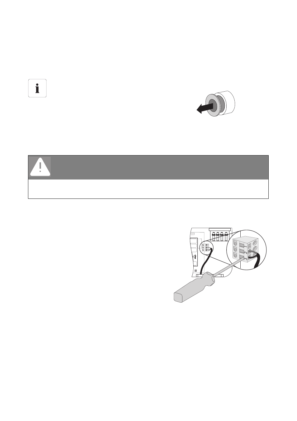
Procedure
1. Disconnect the inverter as described in section 7.2 ”Disconnect the device from voltage
2. Undo the lock nut of the cable gland a little and remove the filler plug from the cable conduit.
3. Pull the cable through.
4. Strip a max. of 8 mm off the insulated wires.
5. Connect wires to the terminal using a screwdriver.
The connection plan shows where the wires must be
connected, depending on whether you require an
operating or an error message.
6. Tighten the lock nut firmly to the cable gland.
7. Re-commission the inverter as described in section 8 ”Restarting the system” (page 62).
8. Switch on supply voltage.
☑ The multifunction relay is now operational.
Seal in the cable gland
There is a two-part seal in the cable
connection. Remove the inner insert of the seal,
if required. This is required to route a thicker
cable.
The following guideline values apply:
• Cable diameter with seal and insert: 5 mm … 7 mm
• Cable diameter with seal and without insert: 7 mm …13 mm
DANGER!
Danger to life due to high voltages in the inverter.
• Use only cables that have been insulated several times.
• Remove a max. of 15 mm cable sheath.