Connections for 8-bit mode – Measurement Computing StrainBook/616 User Manual
Page 98
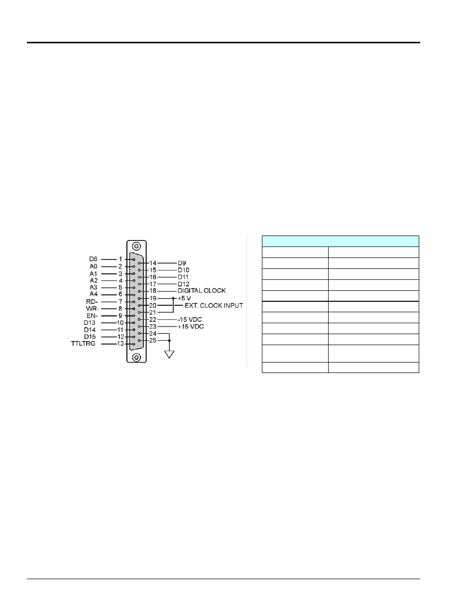
Connections for 8-Bit Mode
To sample just 8 digital input signals use the following pinout, providing that the StrainBook is in 8-bit mode. Note that
WaveView is pre-set to use the 16-Bit mode. In 8-bit mode D15 is the most significant bit, and D8 is the least. The
address lines, read strobe, write strobe, and enable signal can be left disconnected.
o
8 Digital I/O Lines (D8 – D15)
o
5 Address Lines (A0 – A4) *
o
Active-low Digital I/O Enable output (EN-) *
o
Active-low Digital I/O Write Strobe (WR-) *
o
Active-low Digital I/O Read Strobe (RD-) *
o
TTL Trigger Input (TTLTRG)
o
+15 V (pin 23), -15 V (pin 22), 50 mA max. (each)
o
two +5 V power (pins 19 and 21), 250 mA max. (total)
o
two Digital Grounds (pins 24, and 25)
o
Digital Clock (pin 18), only used for WBK17 applications
o
External Clock Input (pin 20)
DB25 Pinout, 8-Bit Mode
D8 through D15
Digital I/O data lines
A0 through A4 *
Digital I/O address lines
EN- *
Active-low digital I/O enable
RD- *
Active-low read strobe
WR- *
Active-low write strobe
TTLTRG
TTL trigger input
+5 VDC
250 mA maximum
+15,-15 VDC
50 mA maximum (each)
Digital Grounds
Pins 24, and 25
Digital Clock
Pin 18, only used for WBK17
applications
External Clock Input
Pin 20
DB25 Pinout for 8-Bit Mode
* Can be left disconnected.
8-2 Digital I/O, TTL Trigger, and External Clock
977794
StrainBook/616