Measurement Computing StrainBook/616 User Manual
Page 29
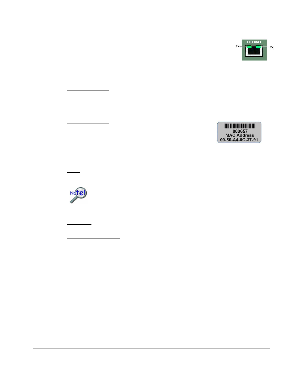
LEDs: There are 5 ETHERNET Status LEDS. Two rectangular LEDs (Tx and Rx) are built into the
frame of the Ethernet jack. The other three LEDs, located just to the right of the jack, are round and are
labeled L, T, and D.
Tx – “ON” indicates traffic is being transmitted (see figure at right).
Rx – “ON” indicates that the port is receiving traffic.
L (Link) “ON” indicates a link exists. “OFF” indicates no link.
T (BaseT) “ON” indicates 100BaseTx, “OFF” indicates 10BaseT.
D (Duplex) “ON” indicates full duplex, which allows simultaneous
two-way data traffic. “OFF” indicates half-duplex, which only allows
one-way data traffic at any given time.
Tx and Rx LEDs
EXPANSION PORT: The 25-pin Expansion Port can be used to connect the StrainBook to a WBK40 or
WBK41 as discussed in chapter 10 of this manual. Refer to the WBK Options Users Manual (489-0902)
for detailed information regarding WBK options. A PDF version of the document is included on your data
acquisition CD.
MAC Address Label: The Media Access Control (MAC) label shows the
device serial number in barcode and base 10 formats. It also shows the
Ethernet address (MAC Address) which is derived from the serial number in
hexadecimal. If prompted to enter a serial number in software, use the base
10 number. Conversion to a hexadecimal number for use in addressing will
be automatic.
Note: If your network administrator asks you for a MAC number or MAC Address, provide the
hexadecimal number that is located at the bottom of the label.
SYNC: (Qty of 2) – Two “synchronization ports” provide a means of synchronizing up to four
StrainBook/616 units in regard to post-trigger scanning. The ports accept CA-74-1 (1 foot) and CA-74-5
(5 foot) cables. Both are 6-conductor RJ-11 cables.
Up to four units can be synchronized. The total combined length of the SYNC cables
is not to exceed 15 feet (4.57 m).
POWER Switch: A rocker-type switch with a “0” label for Power Off, and a “1” for Power On.
POWER IN: +10 VDC to +30 VDC, through a socket type DIN5 connector on the chassis.
Power is typically supplied from a TR-40U power adapter.
EXPANSION CONTROL: The HD15 EXPANSION CONTROL connector provides a means of
connecting a control output signal [from the StrainBook/616 to the 15HD EXPANSION CONTROL IN
connector of the first WBK expansion module used in the system. Expansion Control signal lines can be
daisy-chained, as indicated in Chapter 10, System Examples.
EXPANSION SIGNAL IN: This BNC connector provides a way for the StrainBook/616 to receive return
signals from the EXPANSION SIGNAL OUT BNC connector of the first WBK expansion module in the
system. Expansion Signal lines can be daisy-chained, as indicated in Chapter 10, System Expansion.
StrainBook/616 User’s Manual
967794
Connectors, Indicators, and Cables 3-3