Cn-189, db9 adapter option, Cn-189, db9 adapter option caution – Measurement Computing StrainBook/616 User Manual
Page 77
Cable Pinout
*
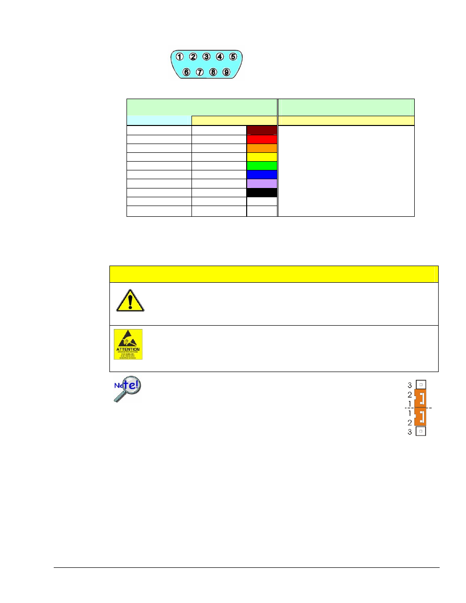
CA-177 Strain-Gage Cable Pinout*
Cable CA-177 Specifications
DB9 Male End (P1)
Unterminated End (P2)
Pin 1
Brown wire
Pin 2
Red wire
Pin 3
Orange wire
Pin 4
Yellow wire
Pin 5
Green wire
Pin 6
Blue wire
Pin 7
Purple wire
Pin 8
Black wire
Pin 9
White wire
Shell Drain
wire
---
P1 Cable End: DB9 male, assembled metal
hood with thumbscrews
(solder cup DB9).
P2 Cable End: Unterminated, blunt cut.
Cable Type: Belden 9614 or equivalent.
Wire Gauge: 24 AWG.
Outer Shield: Foil and 65% braid.
Number of Conductors: Nine (9) plus drain.
Dimensions: Length: 72"
± 4",
Connector width: 1.220" maximum
P1-to-P2 Pinout Specifications:
As indicated at left.
*Cable DB9 numbering is opposite of that found on the StrainBook to allow for correct pin mating.
CN-189, DB9 Adapter Option
CAUTION
Remove the StrainBook from power and disconnect the unit from the host PC and
from all externally connected equipment prior to connecting cables, signal lines,
and/or removing the cover to install or remove components. Electric shock or
damage to equipment can result even under low-voltage conditions.
Take ESD precautions (packaging, proper handling, grounded wrist strap, etc.)
Use care to avoid touching board surfaces and onboard components. Only handle
boards by their edges (or ORBs, if applicable). Ensure boards do not come into
contact with foreign elements such as oils, water, and industrial particulate.
If the CN-189 will be used (a) with a CN-115 installed in the associated
channel, or (b) will be used alone, then the associated channel’s CN-115
header jumpers must be installed as indicated in the figure.
The CN-189 option consists of two 7-pad jumpers (P3 and P4), a DB9 connector, and a 9-slot screw-
terminal block. The adapter plugs into channel input DB9 connectors on StrainBooks and WBK16
expansion modules.
With use of the terminal block and appropriate shorting of jumper pads, the user can easily set up the
desired bridge configuration. A table indicating bridge types and the respective CN-189 jumper pad shorts
follows shortly. In some cases, the user may want to install a resistor at location R1. The electrical
relation of CN-189 components is shown in the following schematic.
StrainBook/616 User’s Manual
929494
Bridge Configurations 6-13