Measurement Computing StrainBook/616 User Manual
Page 107
CE Compliance
If your system needs to be CE Compliant, refer to the Declaration of Conformity for each system
component. Also, refer to Chapter 9, CE Compliance and Noise Considerations.
Associated Cables
DIN5 Note:
3 Return
+10 to +30 V 4
+10 to +30 V 1
2
Return
5 No connection
DIN 5 Power Pinout*
Power is supplied to StrainBook and WBK modules
via a DIN5 type connector located on the rear panel
of the device.
* The DIN5 pinout [to the left] is based on an
external view of a StrainBook rear panel.
Calculate system amp load prior to creating a system daisy-chain. Although StrainBook
and WBK DIN5 connectors and CA-115 and CA-116 power cables have 5 amp limits,
TR-40Us are limited to 3.33 amps @ 15 VDC.
Earlier TR-40U units have a limit of 2.7 A @ 15 VDC. Those supplies still provide
adequate power for StrainBook and WBK16.
Tables for determining amp load are provided in the following section, Calculating System
Power
.
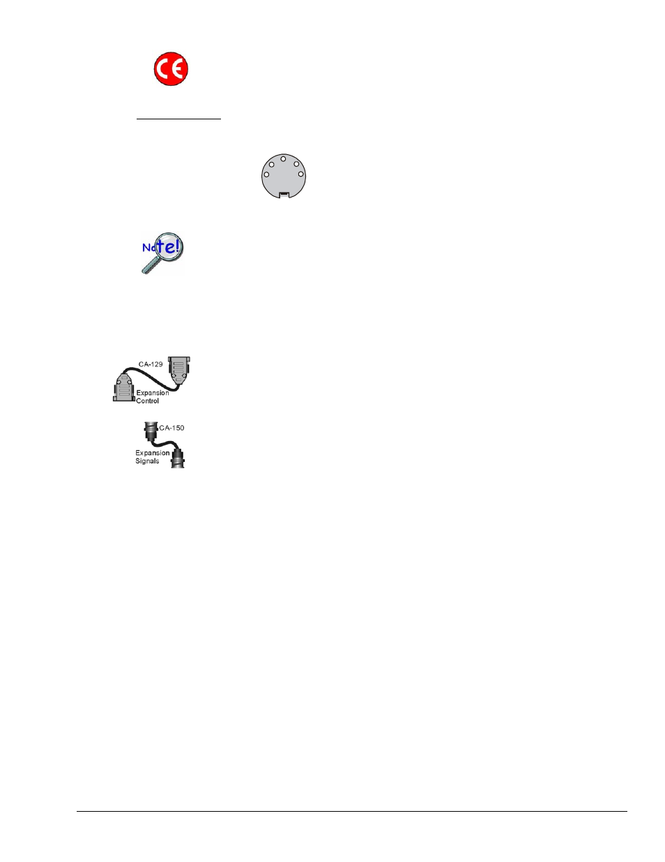
CA-129 Expansion Control Cables.
Control messages are carried by CA-129 expansion-control
cables with HD-15, plug and socket connectors. The first expansion unit’s control input is driven
from the main unit’s control output. Control inputs of additional WBK modules are driven from
the preceding unit’s control output.
CA-150 Expansion Signal Cables.
Expansion signals are carried by a CA-150-1 male BNC to
male BNC coaxial cable. Each WBK module drives a common analog bus that carries the signals
to StrainBook’s Analog-to-Digital Converter (ADC). Each WBK module has EXPANSION
SIGNAL IN and EXPANSION SIGNAL OUT connectors for daisy-chaining multiple units.
CA-242 or
CA-242-7
CA-242 [or CA-242-7] Ethernet patch cable
connects the StrainBook to the host PC’s
Ethernet port or to a network Ethernet hub.
StrainBook/616 User’s Manual
968594
System Expansion 10-3