Measurement Computing StrainBook/616 User Manual
Page 111

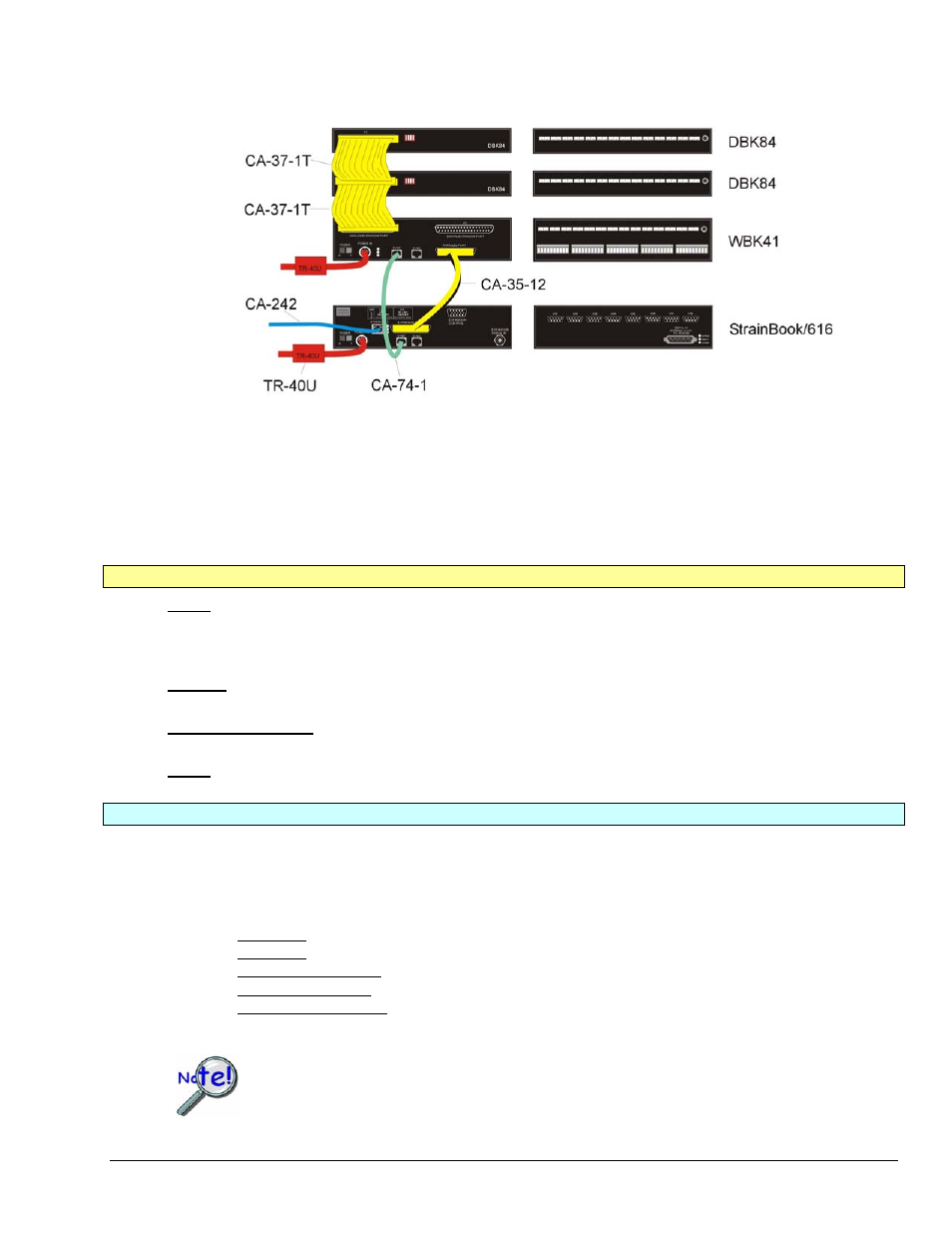
StrainBook, WBK41, DBK84 Daisy-Chain
StrainBook System with a WBK41 and two DBK84 Modules
* Note that earlier TR-40U units have a limit of 2.7 A @ 15 VDC. Those supplies still provide adequate power for StrainBook and WBK16.
TR-40U
3.3 Amp limit
@ 15 VDC *
Device Interface Side Channel Input Side
The illustrated system consists on one StrainBook/616 and two WBK16 Strain Gage Modules.
An explanation of connections follows.
Device Interface Connections
Power – A separate TR-40U power supply is being used for the StrainBook and the WBK41. The DIN5 cable end
of the TR-40U connects POWER IN DIN5 connector on the device. The other end of the
TR-40U connects to an AC outlet (90 to 264 VAC). Note that the two DBK84 modules each get their power
through their P1 connector via the ribbon cable.
Ethernet – The CA-242 [or CA-242-7] Ethernet patch cable connects the StrainBook to the host PC’s
Ethernet port or to a network Ethernet hub.
Expansion to WBK41 – A CA-35-12 [25 conductor] cable connects the WBK41’s PARALLEL PORT to the
StrainBook’s EXPANSION PORT.
SYNC – A CA-74-1 [or CA-74-5] cable is typically used to provide synchronization.
Channel Input Connections
o
14 Thermocouples can be connected to the first DBK84
o
14 Thermocouples can be connected to the second DBK84
o
14 Thermocouples can be connected to the WBK41 (or WBK40).
o
In addition, for WBK41 the following can be connected:
Digital I/O - 16 via front panel screw terminal blocks
Digital I/O – 24 via rear panel P2 (DB37 connector)
Counter Input (CNTR) - 4 via front panel screw terminal blocks
Timer Output (TMR) - 2 via front panel screw terminal blocks
Analog Output (DACS) lines 16-bit, 100 kHz Analog Output via front panel screw-terminal blocks, but
only when a factory-installed DBK46 option is within the WBK41.
WBK40 and WBK41 systems are not supported in WaveView.
StrainBook/616 User’s Manual
968594
System Expansion 10-7
