Excitation connection, Caution – Measurement Computing StrainBook/616 User Manual
Page 69
Excitation Connection
Remote sense inputs are provided for the excitation regulators. The excitation voltage will be most accurate
at points where remote sense lines are connected, preferably at the bridge (this is often referred to as a
6-wire connection). Long cables will reduce the voltage at the bridge, due to current flow and wire
resistance, if remote sense is not used.
If the 6-wire approach is not used, the remote sense inputs must be jumpered to the excitation
outputs at the input connector. Internal 1 MΩ resistors are also connected where the jumpers would be
located to prevent circuit discontinuities. These 1 MΩ resistors are not suitable for high-accuracy
excitation-voltage regulation.
3-wire quarter-bridge configurations do not benefit from external remote sense connections. The lead
resistance is actually a balanced part of the bridge. If the + remote sense input is connected to the + input
on a quarter-bridge, the voltage is regulated across the bridge completion resistor. This results in a
constant-current linearized quarter-bridge; otherwise quarter-bridges are not perfectly linear.
Shunt-Calibration Resistors.
StrainBook provides three physical locations for internal shunt-calibration
resistors for each channel. Each shunt resistor is switched in from the EXCITATION (-) to the IN (+) of
the Instrumentation Amp by a FET switch to create a repeatable bridge imbalance. Internal resistance of
the circuit is about 1 kΩ; the exact amount is automatically accounted for in the software. The software
also allows selection of the three shunt resistors ( B, D, F ). An internal inversion stage insures correct
polarity during the shunt calibration process; which arm is shunted is therefore irrelevant. Header positions
Rb, Rd, Rf correspond to the software shunt resistor selections of B, D, F.
For any balanced bridge, a resistance value can be placed in parallel with one element to create a
predictable imbalance and output voltage. This shunt-resistance value can be calculated by the following
equation, where V
out
is the differential output voltage of the gage.
Example:
R
Shunt
= R
Bridge Arm
[ ( V
Excitation
/ 4 (V
out
)) - 0.5 ]
R
Shunt
= 350 [ ( 10 / 4(0.020)) - 0.5 ] = 43,575Ω
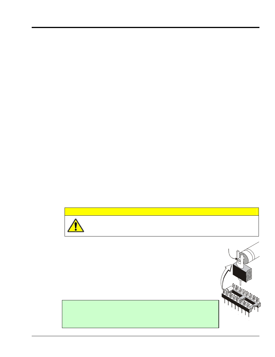
CAUTION
Be careful to avoid component damage while StrainBook enclosure is open. Always
remove bridge completion headers (adapter plugs) from the unit before soldering
resistors in the headers.
Solder resistor lead
into support fork.
Soldering Resistors to
Adapter Plug
Configuring the Bridge Completion Resistor Modules.
For each channel, the
board has a 2×8 resistor socket with rows designated A through H. The removable
adapter plugs are included for soldering in the resistors. Additional adapter plugs
are available for convenient changeover of alternate configurations. Resistor Ra is
located nearest the front panel.
o
Half-bridge completion resistors consist of Rg and Rh.
o
Quarter-bridge completion resistors consist of Ra, Rc, and Re.
o
Shunt resistors consist of Rb, Rd, and Rf.
StrainBook/616 User’s Manual
929494
Bridge Configurations 6-5
Inserting resistors directly into the socket makes an unreliable connection and
is not recommended. Remove the plug from the main board; then solder
resistors to the adapter plug as indicated. To avoid damaging the pin
alignment on the plug, solder with minimal heat. After soldering, the resistor
leads should be snipped off close to the support.