Connecting to the db9 channel input connector, Ca-177 strain-gage cable – Measurement Computing StrainBook/616 User Manual
Page 76
Connecting to the DB9 Channel Input Connector
CAUTION
Remove the StrainBook from power and disconnect the unit from the host PC and
from all externally connected equipment prior to connecting cables, signal lines,
and/or removing the cover to install or remove components. Electric shock or
damage to equipment can result even under low-voltage conditions.
Take ESD precautions (packaging, proper handling, grounded wrist strap, etc.)
Use care to avoid touching board surfaces and onboard components. Only handle
boards by their edges (or ORBs, if applicable). Ensure boards do not come into
contact with foreign elements such as oils, water, and industrial particulate.
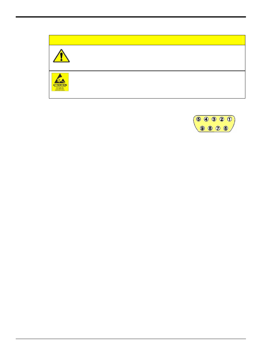
The figure shows the pinout of the DB-9 connector used for channels 1
through 8 located on StrainBook’s front panel. The strain gage will
connect directly to these pin sockets, unless the CN-189, DB9 Adapter
option is used. The CN-189 option is discussed in the following
sub-section.
StrainBook’s DB9 Pinout
A quality cable (such as the CA-177 strain-gage cable) can improve performance of the system, especially
with long cable runs. Use cable with an overall shield connected to the DB9 metal shell. Twisted pair cable
with paired leads for signal input, excitation output, and remote sense input is also beneficial.
The wires should be soldered to the DB9 to eliminate noise created by contact resistance variations. The
protective hoods should be installed over the 9-pin connectors during use to avoid draft-induced thermal-
electric noise in the connector solder joints. Molded cables wider than 1.23 inches will not fit WBK16's
connector spacing.
CA-177 Strain-Gage Cable
Use cable with an overall shield connected to the DB9 metal shell. Twisted pair cable with paired leads for
signal input, excitation output, and remote sense input are also beneficial.
The wires should be soldered to the cable’s DB9 connector to eliminate noise created by contact resistance
variations. The protective hoods should be installed over the 9-pin connectors during use to avoid draft-
induced thermal-electric noise in the connector solder joints.
Molded cables wider than 1.23 inches will not fit the StrainBook’s DB9 connectors due to available space
between the unit’s connectors.
6-12 Bridge Configurations
929494
StrainBook/616 User’s Manual