3 - connectors, indicators, and cables, Front panel connectors and indicators, Connectors, indicators, and cables 3 – Measurement Computing StrainBook/616 User Manual
Page 27
Connectors, Indicators, and Cables
3
Front Panel Connectors and Indicators …… 3-1
Rear Pannel Connectors, Indicators, and Power Switch …… 3-2
Associated Cables …… 3-4
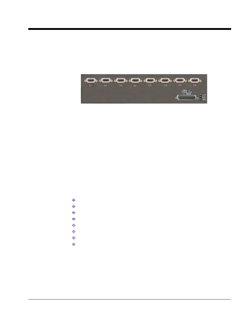
Front Panel Connectors and Indicators
StrainBook/616 Front Panel
CH1 through CH8
Channel Input DB9 Female Connectors: These eight DB9 connectors are used for channel input.
Status LEDS
ACTIVE
– Lights when a sample has been converted by the A/D converter.
READY
– Lights when the unit is fully booted and is ready for software access.
POWER
– Lights when power is turned on and is present.
Digital I/O, External Clock, TTL Trigger
Digital I/O, External Clock Input, and TTL Trigger Input connect to the StrainBook via a front panel
DB25F high-speed digital I/O connector.
For the16-bit mode, which is the default setup for WaveView, the following signals are present on the
DB25.
16 High-Speed Digital I/O Lines (D0 through D15)
TTL Trigger Input (TTLTRG) (pin 13)
+15 V, 50 mA max. (pin 23)
-15 V, 50 mA max. (pin 22)
two +5 V (pin 19 and pin 21), 250 mA max. (total)
External Clock Input (pin 20)
Digital Clock Output (pin 18) –
for WBK17applications only
two Digital Grounds (pins 24 and 25)
To sample just 16 digital input signals, connect them directly to the digital I/O data lines as indicated
in the following pinout. D15 is the most significant bit, and D0 is the least.
StrainBook/616 User’s Manual
967794
Connectors, Indicators, and Cables 3-1