Shunt bcr bcr shunt shunt shunt – Measurement Computing StrainBook/616 User Manual
Page 87
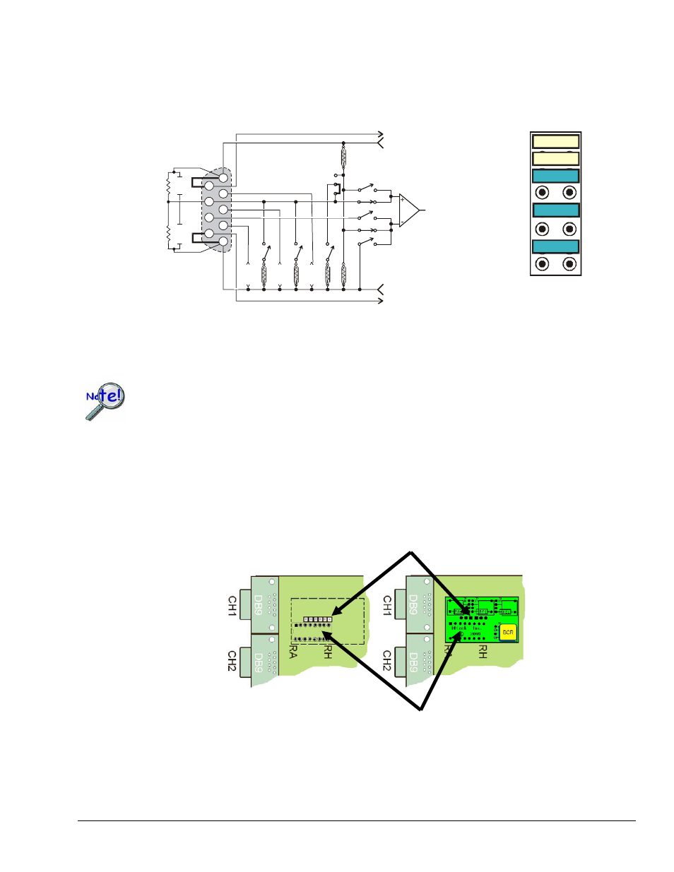
Note that the two half-bridges previously described are identical [circuit wise] to the one illustrated below,
which is being repeated from page 6-6.
The A thru H bridge-completion relations are the same, regardless of whether or not you choose to use a
CN-115-1 plug-in option. Refer to the configuration diagrams to set up your desired circuit(s).
Half-Bridge (+), Any Resistance from 60 to 1000 Ohms,
B,D, or F Shunt
IA
External
Bridge
DB-9
Input
Internal Bridge Completion
RA
RB
RC
RD
RE
RF
RG
RH
1
2
3
-Sense
+Sense
+Excitation
-Excitation
JN01
Switches
accessed
through
software
1
8
9
7
5
4
3
6
2
H
G
F
E
D
C
B
A
Shunt
BCR
BCR
Shunt
Shunt
Shunt
Half-Bridge Circuit Created by using the CN-115 Header Only, i.e., no plug-in card
If present, read the manufacturer’s data that applies to your resistors. Important soldering and
lead-bending information may be present.
CN-115-1 Mounting Orientation
When installing a CN-115-1 be careful to avoid bending the pins and ensure that the card is oriented in relation to
the DB9 connector as indicated below. Note that the associated channel’s two jumpers (located on the StrainBook
board) must be removed.
Jumper Pin Sections Must be Aligned
StrainBook/616 User’s Manual
929494
Bridge Configurations 6-23
No Card Installed Card Installed
The main Pins Must be Aligned with Corresponding Sockets
CN-115-1 Orientation, Shown for Channel 1