Installing a cn-115, Caution – Measurement Computing StrainBook/616 User Manual
Page 70
Installing a CN-115
CAUTION
Remove the StrainBook from power and disconnect the unit from the host PC and
from all externally connected equipment prior to connecting cables, signal lines,
and/or removing the cover to install or remove components. Electric shock or
damage to equipment can result even under low-voltage conditions.
Take ESD precautions (packaging, proper handling, grounded wrist strap, etc.)
Use care to avoid touching board surfaces and onboard components. Only handle
boards by their edges (or ORBs, if applicable). Ensure boards do not come into
contact with foreign elements such as oils, water, and industrial particulate.
Be careful to avoid component damage while the StrainBook is open. Always remove
bridge completion headers (CN-115) from the unit before soldering resistors in the
headers.
Be careful to avoid bending the pins and ensure that the plug-in is correctly oriented.
Note that the associated channel’s two jumpers (located on the StrainBook board)
must be installed for CN-115 applications; but removed for CN-115-1 or WBK16/LC
applications.
You can easily install a CN-115 as follows:
Note: If you need to add or remove resistors to the CN-115 plug-in, do so prior to the installing it.
Configuration diagrams begin on page 6-8.
1. Review the preceding CAUTIONS.
2. Remove the StrainBook [or WBK16] from power and disconnect the unit from all external
devices and signals.
3. Observe proper ESD precautions.
4. Remove the cover from the StrainBook [or WBK16].
5. Locate the CN-115 channel header(s) in which the plug-in is to be installed.
6. If the header socket is occupied, remove the CN-115-1, WBK16/LC, or previous CN-115 to
expose the header socket.
7. Add one shunt jumper to each of the two 3-pin headers. The 3-pin headers are located at the
edge of the CN-115 16-pin header sockets (see figures).
Note: For each channel the jumper headers are labeled in sets of two: JP101/JP102 for
channel 1, through JP801/JP802 for channel 8. The first digit after “JP” signifies the
associated channel number.
8. Carefully plug the CN-115 into the header socket.
9. Re-install the cover to the StrainBook [or WBK16].
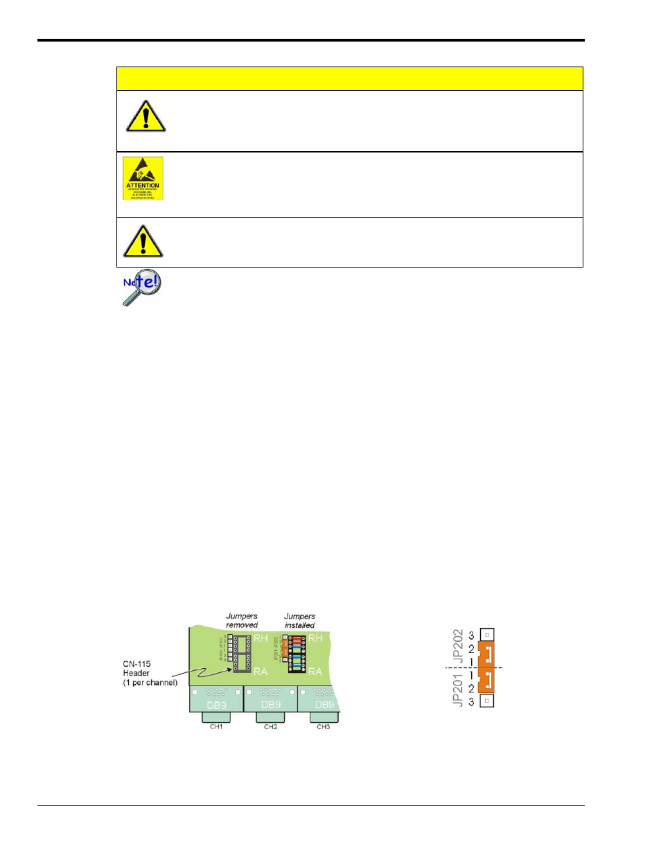
CN-115 Headers for Channels 1 and 2
Channel 1 has jumpers removed. Channel 1 has no
CN-115 installed. Channel 2 shows a CN-115
installed and proper jumper installation.
Required Jumper Placement for CN-115 Plug-in
For each channel that has a CN-115 installed,
pins must be jumpered as indicated above. Each
channel has a jumper header next to the edge of
its CN-115 header.
6-6 Bridge Configurations
929494
StrainBook/616 User’s Manual