6 - bridge configurations, Introduction, Bridge configurations 6 – Measurement Computing StrainBook/616 User Manual
Page 65
Bridge Configurations
6
Introduction …. 6-1
CN-115 Headers, Associated Jumpers, and Plug-In Options …… 6-2
Bridge Applications …… 6-3
Removing the Cover Plate …… 6-4
Excitation Connection …… 6-5
Installing a CN-115 ….. 6-6
Low Pass Filter Customization …… 6-7
Configuration Diagrams …… 6-8
Full-Bridge …… 6-8
Half-Bridge …… 6-9
Three-Wire Quarter-Bridge …… 6-10
High-Gain Amplifier …… 6-11
Connecting to the DB9 Channel Input Connector …… 6-12
CA-177 Strain Gage Cable …… 6-12
CA-189, DB9 Adapter Option …… 6-13
WBK16/LC Load Cell Shunt Cal Internal Option
…… 6-15
CN-115-1 User-Configurable Plug-In Card Option
…… 6-20
Introduction
The strain gage is connected to the amplifiers through the Bridge Completion and Shunt Cal Network. This network
consists of user-supplied / user-installed resistors for bridge completion. Several combinations of resistors and 3
different shunt
values may be installed simultaneously. External connector tie points and the programmable
Input Configuration & Cal
MUX determine the actual configuration in use.
Once the network is fully configured, most bridge configurations and resistances can be accommodated without re-
opening the box. The shunt resistors allow each bridge to be put into a known imbalance condition for setting or
verifying channel calibration. Shunt calibration allows a full-scale gain to be set without physically loading the bridge.
Page 6-12 discusses a DB9 Adapter option that provides a means of easily setting up a bridge configuration.
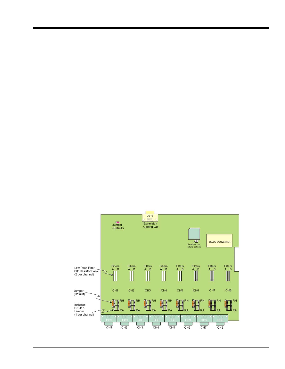
The following board layout shows locations of components referenced to in this chapter. The jumper positions are
default locations. Information regarding the CN-115 header and associated jumpers follows.
StrainBook Board Layout
StrainBook/616 User’s Manual
929494
Bridge Configurations 6-1