I/o board, Leds, Switches – Gasboy CFN Series CFN II Quick Reference User Manual
Page 44: Jumpers
CFN II Quick Reference
40
C09159 Rev. 2238
CMOS CPU Board
Part number: C05321
LEDs
LED
Color
Function
L1 red
422
transmit
L2 red
422
receive
L3, 4, 5, 6
red
submersible & slow flow, pump 1,
2, 3, 4
L7, 8, 9, 10
red
fast flow, pump 1, 2, 3, 4
Switches
DIP switch banks B and C on the CMOS CPU board
set options latched in at power-up time.
DIP Switch Bank B
Position & Definition
Setting(*=customary)
1-4 address
see
below
5 address
*always
closed
6 address
*always
closed
7 baud
rate
*open=9600
closed-see below
8 baud
rate
*closed=9600
open-see below
Baud Rate
B-7
B-8
not used
closed
closed
9600 open closed
1200 closed open
300 open open
Addres
s
B-1
B-2
B-3
B-4
B-5
B-6
1 cl cl cl cl cl cl
2 op cl cl cl cl cl
3 cl op cl cl cl cl
4 op op cl cl cl cl
5 cl cl op cl cl cl
6 op cl op cl cl cl
7 cl op op cl cl cl
8 op op op cl cl cl
9 cl cl cl op cl cl
10 op cl cl op cl cl
11 cl op cl op cl cl
12 op op cl op cl cl
13 cl cl op op cl cl
14 op cl op op cl cl
15 cl op op op cl cl
16 op op op op cl cl
DIP Switch Bank C
Position & Definition
Setting(*=customary)
1-4 pulser
enabled
pumps 1-4
*closed=after reset is
complete
open=upon activation
5 CRC
required
*open=required
closed =not required
6
dead man timer
*always open=enabled
7 ____
8 test
mode
*closed=no
open=yes
Jumpers
Jumper Setting-IN
Setting-OUT
Default
K1 normal
battery
test
installed
K2 battery
no
battery
installed
I/O Board
The part number of the original PPC I/O board is
C05668.
Jumpers
Jumper Position
Position
Default
K1-K4 (see
below)
K-5 in=low
speed
main pulsers
out=high speed
main pulsers
out
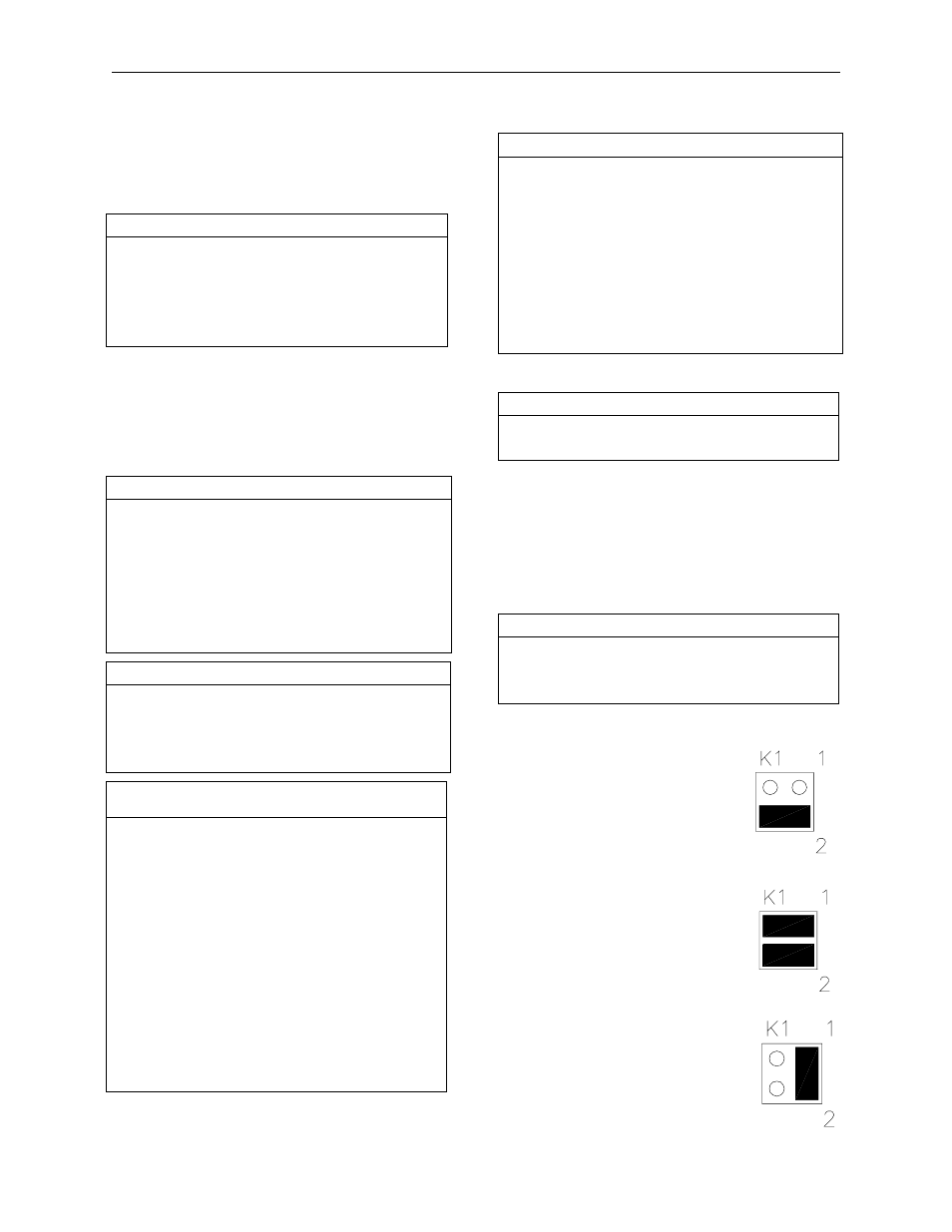
K1-K4 power pulsers 1-4.
For pulsers with mechanical
switch closures (such as VR 1871
series):
For electronic pulsers requiring
+12 Volt power (such as VR 7671
series):
For pulsers with an external power
supply (such as VR 7874 series):