3 asi in/out 1 & 2 connectors, bnc (unused), 4 utility connections, 1 term connector, rj-12 – Comtech EF Data CDM-740 User Manual
Page 46: 2 redundant connector, db-9f
CDM-740 Advanced Satellite Modem
Revision 0
Rear Panel Connector Pinouts
MN-CDM740
3–4
3.3.3
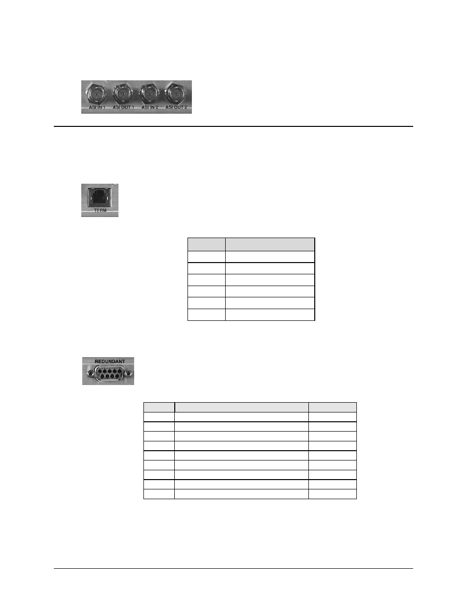
ASI IN/OUT 1 & 2 Connectors, BNC (UNUSED)
This BNC connector group is unused. All information in this
section is provided for reference only.
3.4
Utility Connections
3.4.1
TERM Connector, RJ-12
The TERM Connector is a standard 6-pin RJ-12 female modular jack. It is used for
management of CDM-740 and IP functions using a terminal emulator connected
(with the supplied adapter cable) to the Console port. This is a EIA-232 DCE
interface. Refer to Table 3-2 for the connector pinouts.
Table 3-2. TERM Connector Pin Assignments
Pin #
Function
1 Ground
2 Rx
3 Tx
4 Ground
5 Not
used
6 Not
used
3.4.2
REDUNDANT Connector, DB-9F
The Redundant connector is a 9-pin Type ‘D’ female connector, intended only
for connection to a CRS-175L L-Band 1:1 Redundancy Switch. Refer to Table 3-3
for pinouts.
Table 3-3. REMOTE Connector Pinouts
Pin #
Description
Direction
1 Ground
2
Receive Serial Data – auxiliary channel
In
3
Redundancy In 1
In
4
Redundancy In 2
In
5 Ground
6
Transmit Serial Data – auxiliary channel
Out
7
Redundancy Out 1
Out
8
Redundancy Out 2
Out
9
Fused +12 volt
Out