6 rear panel, 7 data interfaces, 8 verification – Comtech EF Data CDM-740 User Manual
Page 31
CDM-740 Advanced Satellite Modem
Revision 0
Introduction
MN-CDM740
1–7
1.3.6
Rear Panel
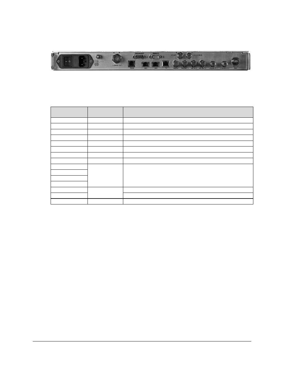
Figure 1-5. CDM-740 – Rear Panel View
Figure 1-5 shows the rear panel of the modem. External cables are attached to connectors on the
rear panel of the CDM-740. For a detailed descriptions/pinouts of each connector, see Chapter 3.
REAR PANEL CONNECTOR PINOUTS.
Ref Des
Connector
Type
Description
L-BAND OUT
Type ‘N’
L-Band Transmit Output
REDUNDANT DB-9F
1:1 Redundancy Interface
REMOTE DB-9M
Remote (Tx, Rx traffic alarms and unit faults)
IF OUT
BNC
IF Transmit Output
L-BAND MON
Type ‘F’
L-Band Monitor Output
TERM RJ-12
Terminal (EIA-232) Interface
GE-1, GE-2
RJ-45 (2X)
(2) 10/100/1000 BaseT Ethernet interfaces (IEEE 802.3ab)
FE RJ-45
10/100 BaseT Ethernet interface (IEEE 802.3u)
ASI IN 1
BNC (4X)
(2) ASI TX Outputs & (2) ASI RX Inputs
(Presently unavailable/unused)
ASI OUT 1
ASI IN 2
ASI OUT 2
L-BAND IN 1
Type ‘F’ (2X)
L-Band Input 1
L-BAND IN 2
Presently unavailable/unused
EXT/INT REF
BNC
Reference: External Input / Internal Output
Note: The European EMC Directive (EN55022, EN50082-1) requires using properly shielded
cables for DATA I/O. These cables must be double-shielded from end-to-end, ensuring a
continuous ground shield.
1.3.7
Data Interfaces
The CDM-740 offers the following data interfaces:
• (2) 10/100/1000 BaseT Gigabit Ethernet Interfaces (GE1, GE2);
• A 10/100 BaseT Gigabit Ethernet Interface for management purposes (Web, SNMP, and
CLI [Command Line Interface]);
• A EIA-232/485 interface for serial modem remote control.
1.3.8 Verification
The CDM-740 includes three test modes for rapid verification of the correct function of the unit.
When normal operation is again selected, all of the previous values are restored.