C.3.2.1 redundancy operation via the front panel – Comtech EF Data CDM-740 User Manual
Page 146
CDM-740 Advanced Satellite Modem
Revision 0
1:1 Redundancy
MN-CDM740
C–6
C.3.2
CDM-740 1:1 Redundancy Operations via the CDM-740
C.3.2.1
Redundancy Operation via the Front Panel
The user can control 1:1 redundant operation via the CDM-740 front panel, using the keypad and
display. Nested menus are used, which display all available options, and prompt the user to carry
out a required action.
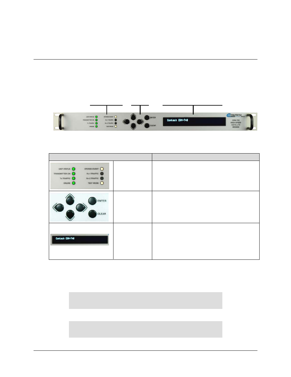
Figure C-5. CDM-740 – Front Panel View
The purpose of the key features of the CDM-740 front panel is summarized as follows:
Feature
Description
LED
Indicators
Used to indicate the operational status of the
CDM-740 Modem.
Keypad
Used to select and navigate the available
CDM-740 menu functions as displayed on the
Vacuum Fluorescent Display (VFD).
Vacuum
Fluorescent
Display (VFD)
Used to fully control and monitor operation of
the CDM-570 Modem. Consisting of two lines
with a width of 24 characters each, nested
menus displayed on the VFD provide all
available options and prompt the user to carrout
out a required action via the keypad.
For complete details on using the CDM-740 front panel, refer to Chapter 5. FRONT PANEL
OPERATIOM in this manual.
To enable 1:1 Redundancy from the CDM-740 front panel, press ENTER or CLEAR until the
Select: (Main) menu is displayed:
Select: Configuration Test Monitor
Store/Ld Utility ODU FAST
(
◄►
)
Use the
◄ ►
arrow keys to select the Utility menu branch, then press ENTER.
Utilities: Set-RTC Display-Brightness
1:1 1:N Circuit-ID Firmware (
◄►
E)
LED
Indicators
Keypad
Vacuum Fluorescent
Display (VFD)