2 receive / demodulator – Comtech EF Data CDM-740 User Manual
Page 35
CDM-740 Advanced Satellite Modem
Revision 0
Introduction
MN-CDM740
1–11
1.5.2
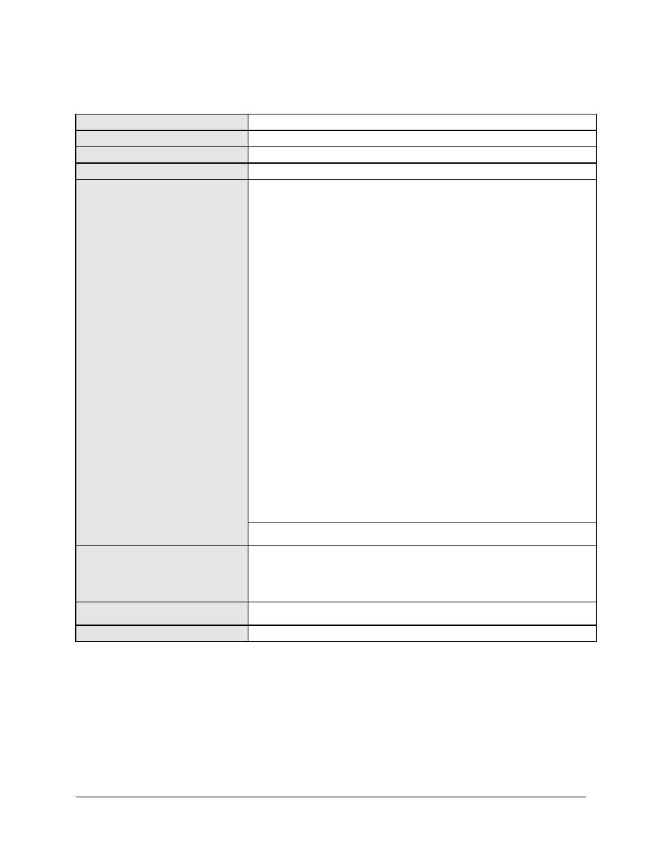
Receive / Demodulator
L-Band Input
950 to 2150 MHz, Type F female
L-Band Input Power Range
-25 to -55 dBm
Data Decapsulation
MPE/IP (ETSI EN 301 192 Multi-Protocol Encapsulation)
FEC
LDPC+BCH: 5 bit soft decision, proprietary
Operating Modes
DVB-S (ETSI EN 300 421):
• Rate QPSK 1/2
• Rate QPSK 2/3
• Rate QPSK 3/4
• Rate QPSK 5/6
• Rate QPSK 7/8
DVB-S2 (ETSI EN 302 307):
• Rate QPSK 1/4
• Rate 8-PSK 9/10
• Rate QPSK 1/3
• Rate 16-APSK 3/5
• Rate QPSK 1/2
• Rate 16-APSK 2/3
• Rate QPSK 3/5
• Rate 16-APSK 3/4
• Rate QPSK 2/3
• Rate 16-APSK 5/6
• Rate QPSK 3/4
• Rate 16-APSK 8/9
• Rate QPSK 5/6
• Rate 16-APSK 9/10
• Rate QPSK 8/9
• Rate 32-APSK 3/5
• Rate QPSK 9/10
• Rate 32-APSK 2/3
• Rate 8-PSK 3/5
• Rate 32-APSK 3/4
• Rate 8-PSK 2/3
• Rate 32-APSK 5/6
• Rate 8-PSK 3/4
• Rate 32-APSK 8/9
• Rate 8-PSK 5/6
• Rate 32-APSK 9/10
• Rate 8-PSK 8/9
Note: Refer to Table 5-2 through Table 5-4 for additional data rate/symbol rate
information.
LNB 10 MHz Reference
On center conductor of L-Band input connector, selectable ON/OFF.
Level: -3dBm
± 3 dB.
Source: either Internal modem reference or External reference
Performance: For phase noise, refer to L-Band modulator 10 MHz Frequency
stability same as the modulator 10 MHz reference.
LNB Voltage
On center conductor of L-Band input connector, selectable ON/OFF, 13, 18 volts
per DiSEq 4.2 and 24VDC at 500 mA maximum.
LNB Current Alarm
Programmable MIN and MAX current alarms.