7 ds07 15-pin female hd ‘d’ sub connector (j13) -9, 8 ds08 15-pin female hd ‘d’ sub connector (j14) -9, 12 optical/oc3 stm-1 rear panel interface -9 – Comtech EF Data MM200 User Manual
Page 85: 1 elec out female bnc connector (j15) -9, 2 elec in female bnc connector (j16) -9, 3 optical in sc connector (j17) -9, 4 optical out sc connector (j18) -9, 5 ref out female bnc connector (optional) (j19) -9, 6 ref in female bnc connector (optional) (j20) -9
MM200 High-Speed Microwave Modem
Electrical Interfaces
TM086 - Rev. 4.1
5-9
5.11.7 DS07 15-pin female HD ‘D’ sub connector (J13)
Provides Channel 7 DS0 Interface.
5.11.8 DS08 15-pin female HD ‘D’ sub connector (J14)
Provides Channel 8 DS0 Interface.
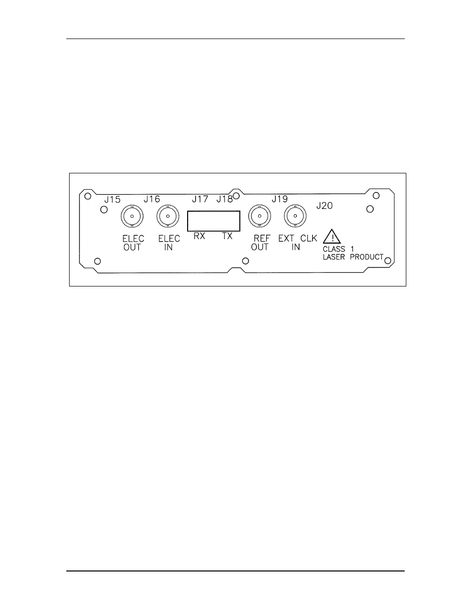
5.12 Optical/OC3 STM-1 Rear Panel Interface
This rear panel interface (Figure 5-5) provides OC3 Optical or STM1 Electrical Interface.
Figure 5-5. Optical/OC3 STM-1 Rear Panel Interface
5.12.1 ELEC OUT Female BNC Connector (J15)
Provides STM1 Data Output from the receiver.
5.12.2 ELEC IN Female BNC Connector (J16)
Accepts STM1 Data Input to be transmitted.
5.12.3 OPTICAL IN SC Connector (J17)
Accepts OC3 Data Input to be transmitted.
5.12.4 Optical Out SC Connector (J18)
Provides OC3 Data Output from the receiver.
5.12.5 REF OUT Female BNC Connector (Optional) (J19)
Provides Reference Clock Output.
5.12.6 REF IN Female BNC Connector (Optional) (J20)
Accepts the Reference Clock Input.