3 terminal port (i/o) -3, 4 remote port (i/o) -3 – Comtech EF Data MM200 User Manual
Page 79
MM200 High-Speed Microwave Modem
Electrical Interfaces
TM086 - Rev. 4.1
5-3
5.3 Terminal Port (I/O)
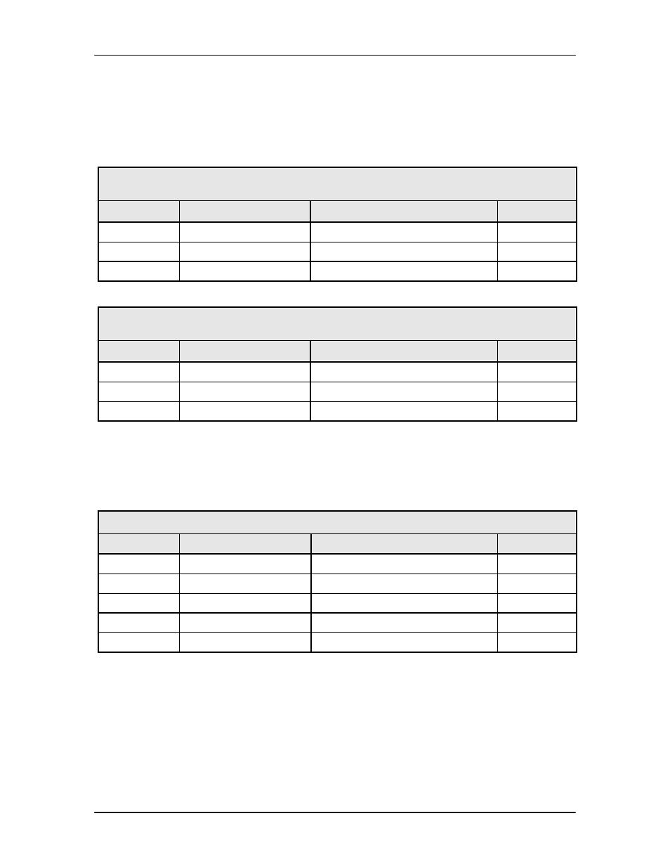
The Terminal Port (J2) can be used for the monitor & control functions of the unit. The physical
interface is a female 9-Pin D-Sub Connector. This bi-directional port complies with RS-232
Electrical Specifications. The pinouts are listed in Table 5-4a and 5-4b. S3 can be found on the
M&C Card by removing the top cover.
Table 5-4a. J2 - RS-232 Terminal Port - 9-Pin ‘D’ Female
S3 – Switch 1 & 2 Off, Switch 3 & 4 On
Pin No.
Signal Name
Description
Direction
2
TxD
Transmit Data
Output
3
RxD
Receive Data
Input
5
GND
Ground
---
Table 5-4b. J2 - RS-232 Terminal Port - 9-Pin ‘D’ Female
S3 – Switch 1 & 2 On, Switch 3 & 4 Off
Pin No.
Signal Name
Description
Direction
2
RxD
Receive Data
Input
3
TxD
Transmit Data
Output
5
GND
Ground
---
5.4 Remote Port (I/O)
The Remote Port (J3) can be used for the monitor & control functions of the unit. The physical
interface is a female 9-Pin D-Sub Connector. This bi-directional port complies with RS-485
Electrical Specifications. Pin-outs are listed in Table 5-5.
Table 5-5. J3 - RS-485 Remote Control - 9-Pin ‘D’ Female
Pin No.
Signal
Description
Direction
1
Tx (B)
Transmit Data (+)
Output
5
GND
Ground
-
6
Tx (A)
Transmit Data (-)
Output
8
Rx (B)
Receive Data (+)
Input
9
Rx (A)
Receive Data (-)
Input