AMETEK i-iX Series II User Manual
Page 40
User Manual
California Instruments
40
i Series II / iX Series II / iM Series II
3.6.6 I/O Option – J58
This connector is reserved for control of the EOS option. Do not connect anything else to this
connector.
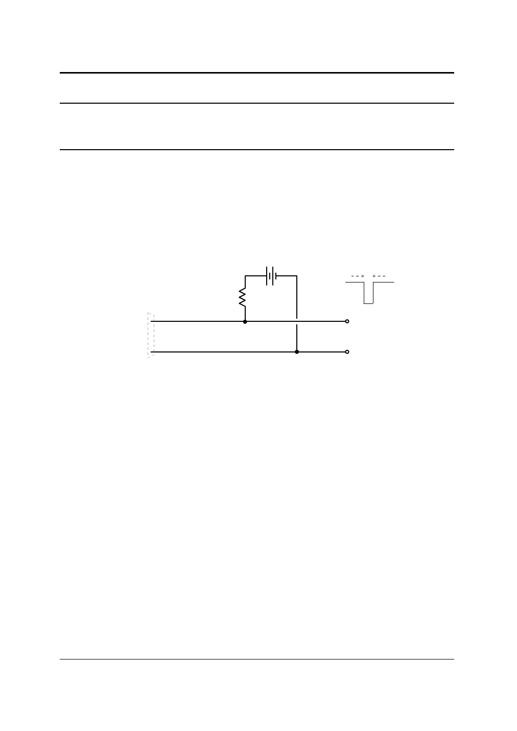
3.6.7 Function Strobe / Trigger Out – J22-31 / J22-14
A function strobe output is available on the System Interface connector. This open collector output
may be used to trigger external equipment when voltage or frequency change occurs on the AC
source.
This output generates a low-going pulse, > 400
µ
s in duration, that indicates voltage or frequency
change. Since this is an isolated output, an external DC supply and pull-up resistor, 22K
Ω
, 1/8 W is
required. To create a TTL level output, a +5V or +3.3V DC supply is required. To create a signal for
viewing on a scope, a higher DC voltage such as a 9V battery may be used.
Connect the DC supply and pull-up resistor as shown.
Figure 3-4: Function Strobe Connection.
When running list transients on the AC source, the LIST:TTLTrigger SCPI command may be used
reassign the operation of the Function Strobe output as a trigger output. An output pulse is
generated for each logic “1” in the TTLTrigger list. See the iX/i Series Programming Manual P/N
7000-982 for details on the transient list system.
Trigger BNC Breakout Box
A convenient trigger BNC breakout box is available from California Instruments which facilitates
connection to the Function Strobe / Trigger Output signal on the system interface connector. A 9V
DC battery is used to provide the required DC supply. This small box can be ordered through
customer service or sales under P/N 7000-481-1 (for 3001i/iX and 5001i/iX) or P/N 7000-481-2 (for
all multi-chassis i/iX systems).
+ 5 Vdc
J22-31
J22-14
Function Strobe
High
Function Strobe
Common
Centronics
Connector
System
Interface
+5
0
> 400 uS