AMETEK i-iX Series II User Manual
Page 35
User Manual
California Instruments
i Series II / iX Series II / iM Series II
35
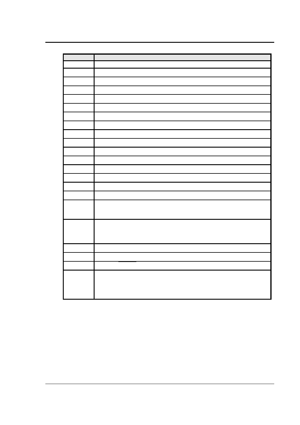
J22
Description
J22-32.
16
AMP SHARE B
17
PARALLEL
18
CL ENA
19
MR C: Phase C master signal
20
MR A: Phase A master signal
21
CS C: Phase C current sum
22
CS A: Phase A current sum
23
OSC C: Phase C oscillator output
24
OSC A: Phase A oscillator output
25
CL C: Phase C current limit reference
26
CL A: Phase A current limit reference
27
D COM: Digital Common
28
RNG HI: Voltage range state: Logic HI = high range, LOW = low range
29
Overload
30
FLT B: Phase B current limit fault control
31
F STB HI: Function Strobe / Trigger output HI. A low-going pulse, >400
µ
s, that indicates
voltage or frequency change. Isolated output that requires a pull-up resistor, 22K
Ω
, to +5
VDC. Use J22 pin 14 (F STB LO) for common. See section 3.6.7 for details.
32
EX SYNC HI, External Sync input HI. This is an input that can be used to synchronize the
outputs of the AC Power System. This input requires a logic high level of at least +4.5
VDC at 5 mA. The input should have a duty cycle 50
±
30%. J22-15 is the common input.
The External Sync input is optically isolated. It must be enabled from the SNC screen.
33
AMP SHARE C
34
AMP SHARE A
35
FLICKER / BYPASS
36
REMOTE ON: This is a logic input that can be used to remove the programmed output
voltage. A logic low on this pin will cause the output voltages to be programmed to 0.0
volts and the output relays to open. A logic high will cause the programmed output voltage
to be restored at the output terminals. A contact closure between this pin and J22-27 (D
COM) will simulate a logic low state.