AMETEK i-iX Series II User Manual
Page 111
User Manual
California Instruments
i Series II / iX Series II / iM Series II
111
the MEAS key may not always bring up the selected screen immediately. There will be a
perceptible delay. This will prevent the screen from appearing with invalid or blank readouts.
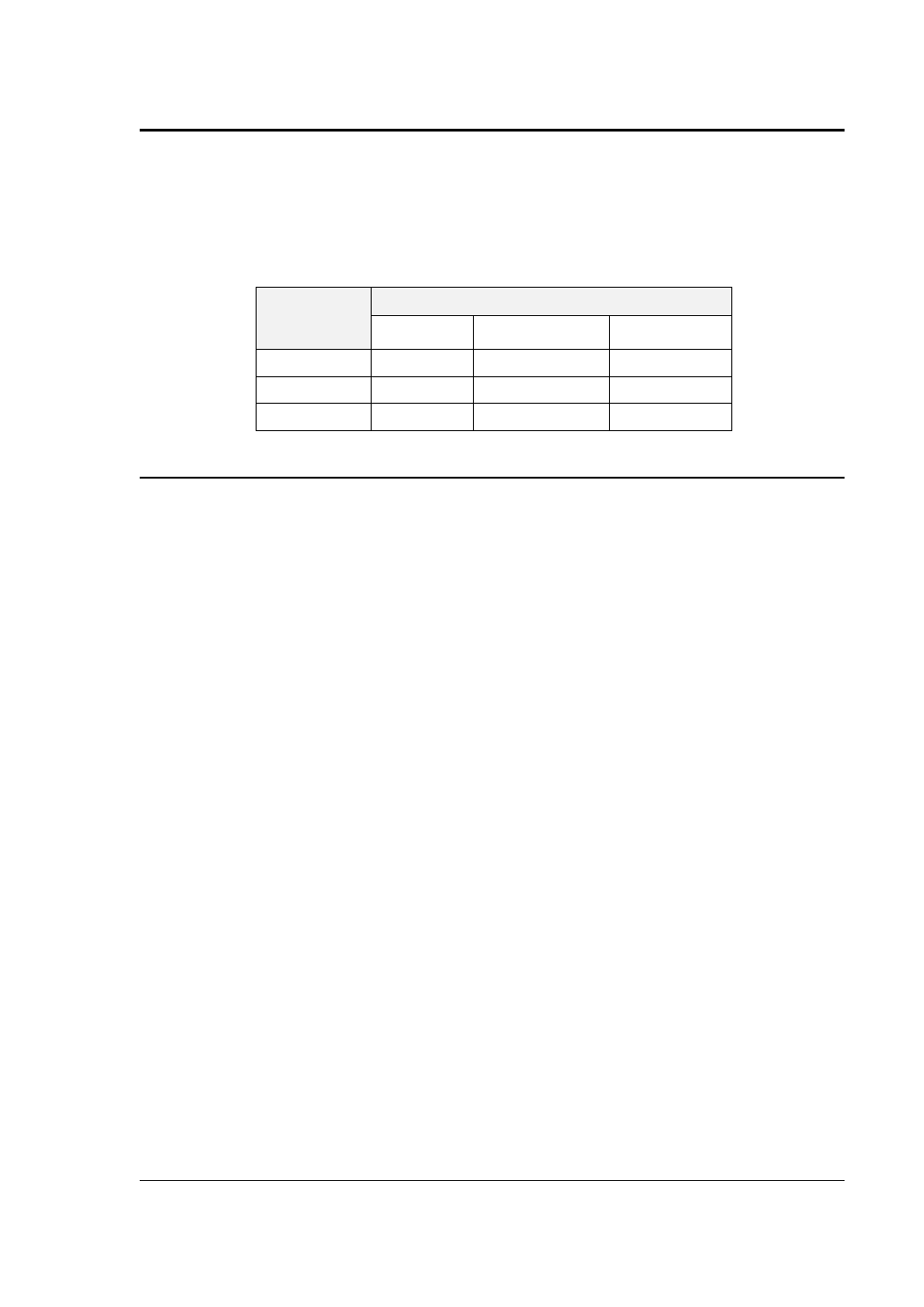
The measurement method for voltage and current will depend on the power source operating
mode. The following table shows the return value type (rms or average) and method of coupling
when the measurement command is initiated with a different extension at various operating
modes (AC, DC or AC + DC).
Measurement
Extension
and Coupling
Operating Mode
AC
DC
AC + DC
AC
rms
rms
rms
DC
rms
rms
average
Coupling
AC
DC
DC
4.5.3 Accuracy Considerations
Any measurement system has a finite accuracy specification. Measurement specifications are
listed in Section 2. When using the AC source for measurement purposes, always consider
these specifications when interpreting results. Measurement inaccuracies become more
pronounced as the signal being measured is at the low end of the measurement range. This is
particularly relevant for low current measurements. The i and iX Series are high power AC
sources optimized for providing and measuring high load currents. When powering low power
loads, measurement inaccuracies on rms and peak current measurements will greatly affect
derived measurements such as power, power factor and crest factor.
The measurement system on the i and iX Series II uses a data acquisition system with a 16 kHz
bandwidth. This means that high frequency components of the measured signal are filtered out.
Any contribution to the rms value of voltage and current above this cutoff frequency will not be
reflected in the i and iX Series measurements. When using an external measurement reference,
this may account for discrepancies in readings.