AMETEK i-iX Series II User Manual
Page 237
User Manual
California Instruments
i Series II / iX Series II / iM Series II
237
1. Steady State Voltage test
2. Ripple test
9.8.1.4.2 EMERGENCY TEST
AC Mode:
1. Emergency Voltage minimum and maximum test
2. Emergency Frequency minimum and maximum test
DC Mode:
1. Emergency Voltage minimum and maximum test
9.8.1.4.3 ABNORMAL TEST
AC Mode:
1. Abnormal Voltage under
2. Abnormal Voltage over
3. Abnormal Frequency under
4. Abnormal Frequency under
DC Mode:
1. Abnormal Voltage under
2. Abnormal Voltage over
9.8.1.5 Front Panel Entry
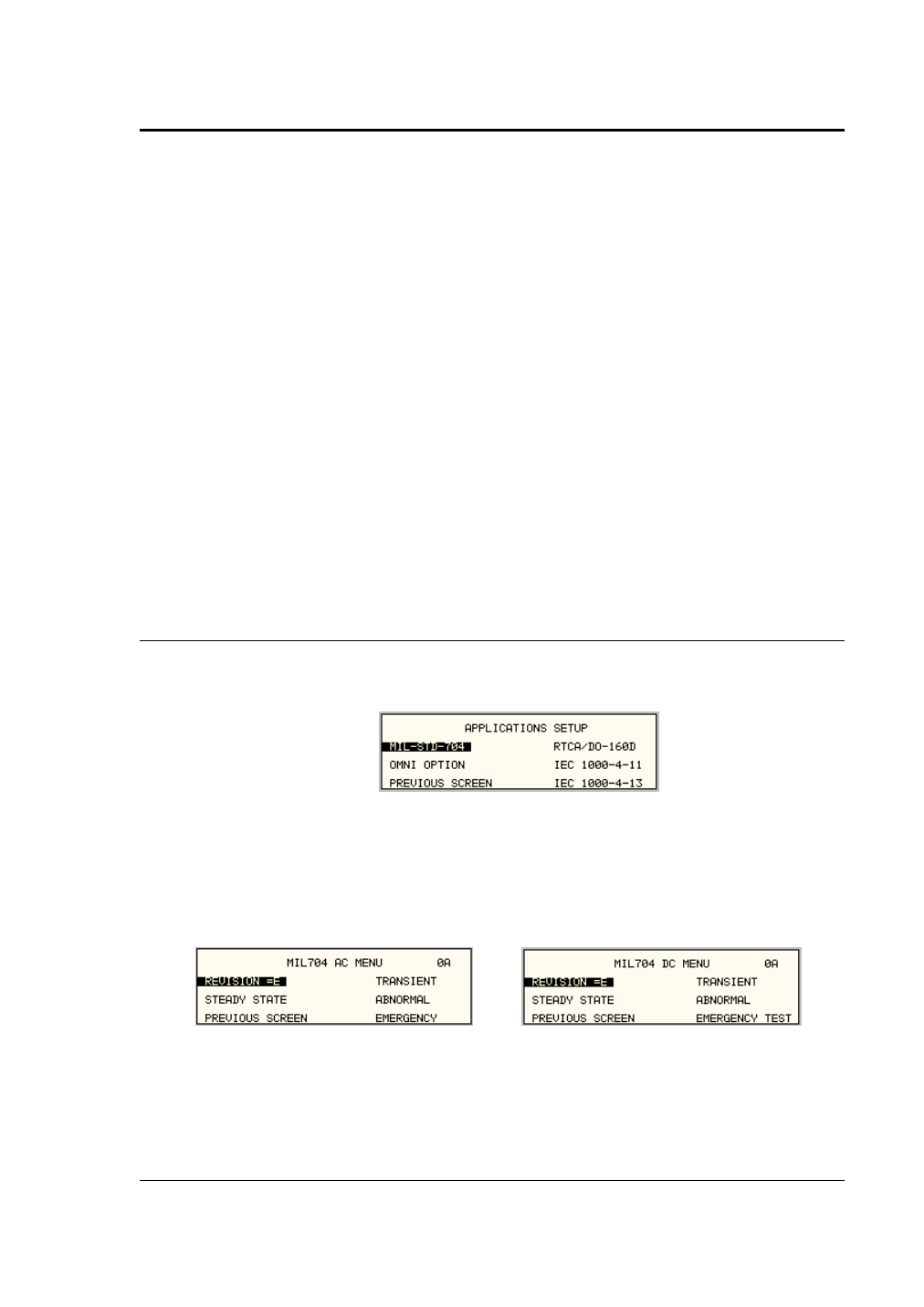
To perform a test from the keyboard, from the MENU 2 screen, select the APPLICATIONS
screen. The APPLICATIONS screen will appear as shown in Figure 9-48.
Figure 9-48: Application Menu
Scroll to the MIL-STD-704 entry using the up and down cursor keys. Press the ENTER key to
select the MIL704 main menu. One of the screens will appear as shown in Figure 9-49. The
voltage mode and setting will define which menu to select. Refer to Section 9.8.1.2
Note: The user has to turn on the Output relay before starting a test and set the steady state
setup for the test.
Figure 9-49: MIL704 Menu