AMETEK i-iX Series II User Manual
Page 146
User Manual
California Instruments
146
i Series II / iX Series II / iM Series II
These pots were originally adjusted at the factory and normally do not have to be adjusted
again. The Full Scale calibration coefficients should have enough adjustment range. Double
check the connections and phase measurements if this is not the case to make sure the
measurement readings you get are indeed correct.
If it is necessary to adjust the pots, see Table 6-4 for the corresponding pot designators. The
top cover has to be removed to access these pots. They are located along the top edge of
the 7003-718 controller board.
11. Repeat steps 2 through 10 for phase B and C. (except on single phase only models.)
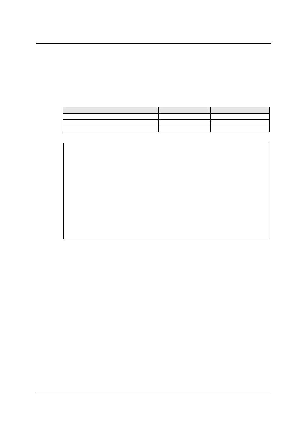
Phase / Board Assembly #
R resistive
Xl inductive
Phase A (7003-718-1 / 7003-718-3)
R121
R122
Phase B (7003-718-1)
R112
R111
Phase C (7003-718-1)
R114
R115
Table 6-4: Programmable Z adjustment pots
Definitions:
V
NL
= Measured RMS voltage under no load.
V
L
= Measured RMS voltage under load
I = Measured RMS current.
F = Source frequency (50 Hz).
∆Φ
= Phase angle shift between load and no load conditions. Record phase angle
from phase meter under NL and L condition and determine phase shift.
Formulas to calculate R and L component of output impedance:
R = ( V
NL
* cos(
∆Φ
) - V
L
) / I
X
L
= ( V
NL
* sin(
∆Φ
)) / I
L = X
L
/ (2 * Pi * F)
Table 6-5: Formulas to calculate R and L