Echelon FT 3150 Smart Transceiver User Manual
Page 99
FT 3120 / FT 3150 Smart Transceiver Data Book
93
Interface between Smart Transceivers and the Network
The T1 and T2 signals are each brought out of the FT-X1 transformer at two different sets of pins. The T1 and T2
connections between the FT-X1 transformer and the FT Smart Transceivers can be made via either set of pins on
the FT-X1 transformer, but the connections shown in the PCB layout figures later in this chapter generally give the
best ESD transient immunity. T1 and T2 were used in FTT-10A transceiver-based designs for ESD clamping only,
but now they are also connected directly to the FT Smart Transceivers via the old RXD and TXD signals of the
Neuron Chip.
The FT-X2 transformer has only one set of T1 and T2 pins, corresponding to pins 5 and 6 on the FT-X1
transformer. Therefore, connection to FT Smart Transceivers, ESD protection circuitry, and C5/C6 capacitors are
all connected through the same set of T1 and T2 pins.
Since the T1 and T2 lines are analog connections between the FT Smart Transceiver and the FT-X1 transformer, no
other parallel connections should be made to these lines (other than the C5 and C6 capacitors and ESD protection
diodes shown in Figure 4.1), and no components should be placed in series between the FT Smart Transceiver and
the FT-X1or FT-X2 transformer. In particular, no RXD/TXD sensing circuitry should be attached to these lines.
There is now an explicit RXD/TXD signal available on the COMM_ACTIVE pin of the FT Smart Transceiver that
can be used for the purpose of driving RXD and TXD LEDs, if desired. See the following section for more
information about the COMM_ACTIVE LED drive circuit.
Interface between Smart Transceivers and the
Network
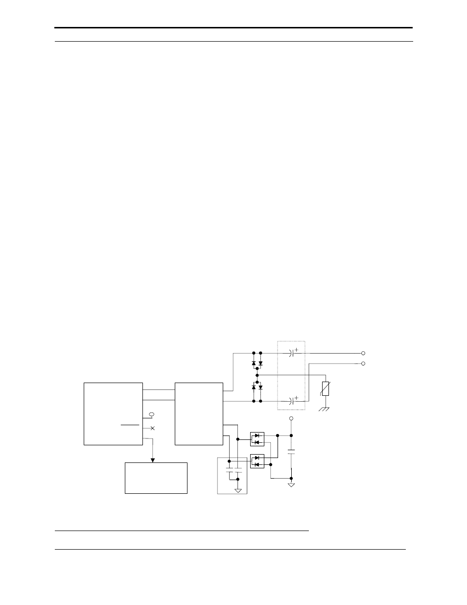
The preferred interconnection between the FT-X1 or FT-X2 transformer, an FT Smart Transceiver, and the
associated transient protection circuitry is shown in Figure 4.1. When using the FT-X1 transformer, pins 3 and 4 are
connected to the Smart Transceiver as shown in the figure, while ESD protection diodes are connected to pins 5
and 6. The FT-X2 transformer does not have pins 3 and 4. Connections to the Smart Transceiver and to the ESD
protection on FT-X2 are both done via pins 5 and 6. Figure 4.1 is not a complete schematic, since it does not
include the clock, reset, and power supply bypass circuits for the FT Smart Transceivers. Refer to the FT 3120 and
FT 3150 Smart Transceiver Datasheet for this additional information.
Figure 4.1 FT Smart Transceiver and FT-X1 or FT-X2 Interconnections with Transient Protection
Circuitry
C1
D2
+5V
D1
NET1
NET2
See
Text
C3
C4
VR1
NET_A
NET_B
T1
T2
T1
T2
FT-X1 or FT-X2
Transformer*
T1
T2
RTMP
COMM_ACTIVE
FT 3120 Transceiver
FT 3150 Transceiver
(Partial)
3
4
+5V
Optional
COMM_ACTIVE
LED Drive Circuit
2
1
5
6
SLEEP
D3
D4
D5
D6
C5
C6
See
Text
*Use pins 5 & 6 for FT-X2