Byte input/output – Echelon FT 3150 Smart Transceiver User Manual
Page 47
FT 3120 / FT 3150 Smart Transceiver Data Book
41
Direct I/O Objects
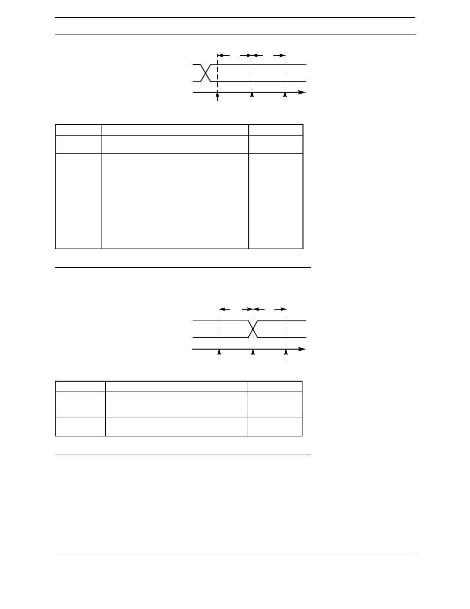
Figure 3.6 Bit Input Latency Values
Figure 3.7 Bit Output Latency Values
Byte Input/Output
Pins IO0 – IO7 may be configured as a byte-wide input or output port, which may be read or written using integers in
the range 0 to 255. This is useful for driving devices that require ASCII data, or other data, eight bits at a time. For
example, an alphanumeric display panel can use byte function for data, and use pins IO8 – IO10 in bit function for
Symbol
Description
Typ @ 10MHz
t
fin
Function call to sample
IO0 – IO10
41 µs
t
ret
Return from function
IO0
IO1
IO2
IO3
IO4
IO5
IO6
IO7
IO8
IO9
IO10
19 µs
23.4 µs
27.9 µs
32.3 µs
36.7 µs
41.2 µs
45.6 µs
50 µs
19 µs
23.4 µs
27.9 µs
Symbol
Description
Typ @ 10MHz
t
fout
Function call to update
IO3 – IO5
All others
69 µs
60 µs
t
ret
Return from function
IO0 – IO10
5 µs
t
ret
t
fin
TIME
INPUT PIN
SAMPLED
END OF
io_in()
START OF
io_in()
INPUT
OUTPUT PIN
UPDATED
END OF
io_out()
START OF
io_out()
t
ret
t
fout
TIME
OUTPUT