I2c input/output, C input/output – Echelon FT 3150 Smart Transceiver User Manual
Page 65
FT 3120 / FT 3150 Smart Transceiver Data Book
59
Serial I/O Objects
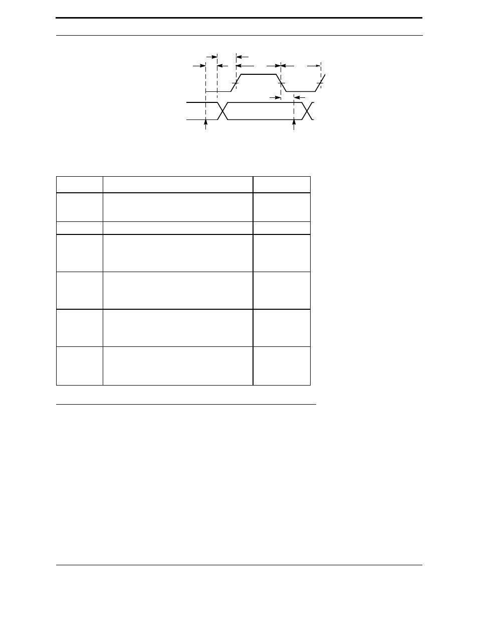
Figure 3.24 Bitshift Output Latency Values
I
2
C Input/Output
This I/O object is used to interface the FT Smart Transceiver to any device which adheres to the Philips
Semiconductor Inter-Integrated Circuit (I
2
C) bus protocol. The FT Smart Transceiver is always the master, with IO8
being the serial clock (SCL) and IO9 the serial data (SDA). These I/O lines are operated in the open-drain mode in
order to accommodate the special requirements of the I
2
C protocol. With the exception of two pull-up resistors, no
additional external components are necessary for interfacing the FT Smart Transceiver to an I
2
C device.
Up to 255 bytes of data may be transferred at a time. At the start of all transfers, a right-justified 7-bit I
2
C address
argument is sent out on the bus immediately after the I
2
C “start condition.”
For more information on this protocol, refer to the Philips Semiconductor I
2
C documentation.
Symbol
Description
Typ @ 10MHz
t
fin
Function call to first data out stable
16-bit shift count
1-bit shift count
185.3 µs
337.6 µs
t
ret
Return from function
10.8 µs
t
setup
Data out stable to active clock edge
15 kbps bit rate
10 kbps bit rate
1 kbps bit rate
10.8 µs
10.8 µs
10.8 µs
t
aet
Active clock edge to next clock transition
15 kbps bit rate
10 kbps bit rate
1 kbps bit rate
10.2 µs
42 µs
939.5 µs
t
tae
Clock transition to next active clock edge
15 kbps bit rate
10 kbps bit rate
1 kbps bit rate
34.8 µs
34.8 µs
34.8 µs
f
Clock frequency = 1/(t
aet
+ t
tae
)
15 kbps bit rate
10 kbps bit rate
1 kbps bit rate
22 kHz
13 kHz
1.02 kHz
DATA OUT
t
aet
Active clock edge assumed to be positive in the above
diagram
t
tae
t
setup
OUTPUT
CLOCK
END OF
io_in()
START OF
io_in()
t
ret
t
fin