Grounding shielded twisted pair cable – Echelon FT 3150 Smart Transceiver User Manual
Page 120
Chapter 5 - Network Cabling and Connections
114
FT 3120 / FT 3150 Smart Transceiver Data Book
Only one LPI-10 interface is supported per segment. The LPI-10 contains the two required terminators. The other
terminator must be an RC-type (see figure below).
Figure 5.6 Twisted Pair Termination Network
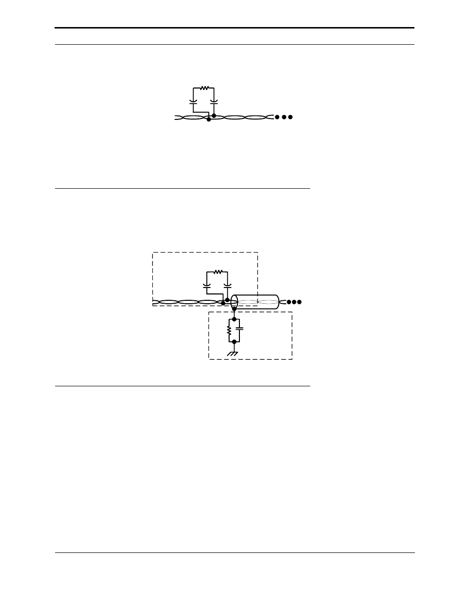
Grounding Shielded Twisted Pair Cable
When using shielded twisted pair, terminate the twisted pair and ground the cable shield, as shown in Figure 5.7.
Figure 5.7 Terminating and Grounding Shielded Twisted Pair Cable
The twisted pair is terminated according to the guidelines listed in the previous sections. The cable shield should be
grounded using a capacitor to tie the shield to earth ground, and a large-value resistor to bleed off any static charge on
the shield.
Tie the shield to earth ground through a capacitor, instead of a direct connection, in order to avoid DC and 50/60 Hz
ground paths from being formed through the shield. Typical values for Rb and Cc are as follows:
Cc = 0.1
µF, 10%, Metalized Polyester, ≥ 100V
Rb = 470k
Ω, 1/4W, ±5%
The cable shield should be grounded at least once per segment, and preferably at each device.
Unshielded
Twisted Pair
(UTP)
Ra
Ca
100µF
50Vmin
Cb
100µF
50Vmin
+
+
Notes:
•
Ca and Cb are typically aluminum-electrolytic
type for improved longevity in the presence of
ESD – observe polarity.
Shielded
Twisted Pair
(STP)
Ca
100µF
50Vmin
Rb
Cc
Cb
100µF
50Vmin
Ra
Twisted Pair
Termination Circuit
Shield
Grounding
Circuit