Quadrature input – Echelon FT 3150 Smart Transceiver User Manual
Page 84
Chapter 3 - Input/Output Interfaces
78
FT 3120 / FT 3150 Smart Transceiver Data Book
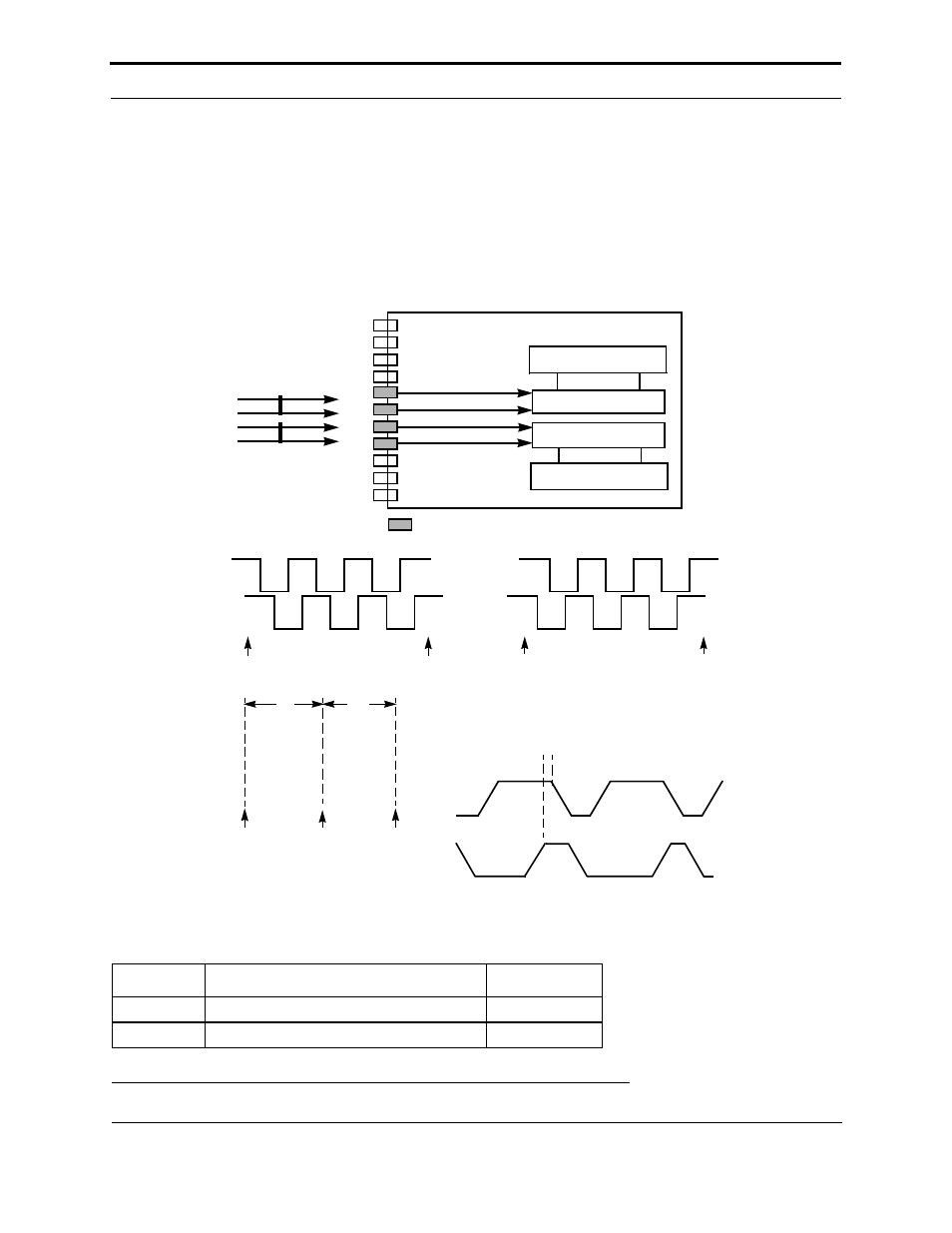
Quadrature Input
A timer/counter may be configured to count transitions of a binary Gray code input on two adjacent input pins. The
Gray code is generated by devices such as shaft encoders and optical position sensors which generate the bit pattern
(00,01,11,10,00, …) for one direction of motion and the bit pattern (00,10,11,01,00, …) for the opposite direction.
Reading the value of a quadrature object gives the arithmetic net sum of the number of transitions since the last time
it was read (– 16,384 to 16,383). The maximum frequency of the input is one-quarter of the input clock rate, for
example 2.5MHz at 10MHz FT Smart Transceiver input clock. Quadrature devices may be connected to timer/
counter 1 via pins IO6 and IO7, and timer/counter 2 via pins IO4 and IO5. If the second input transitions low while
the first input is low and high while the first input is high, the counter counts up. Otherwise, the count is down.
Figure 3.42 Quadrature Input Latency Values
Symbol
Description
Typ @ 10MHz
t
fin
Function call to input sample
90 µs
t
ret
Return from function
88 µs
A
B
read, reset
read, reset
read, reset
read, reset
t
ret
t
fin
READ
TIMER/COUNTER
FLAG AND
EVENT
REGISTER
CLEAR FLAG
END OF
io_in()
START OF
io_in()
Count + 6 counts
Count – 6 counts
Timer/Counter 1
Timer/Counter 2
Event Register
Event Register
IO10
IO9
IO8
IO0
IO1
IO2
IO3
IO4
IO5
IO6
IO7
2 x CLK1 Period, Ex: 200 ns @ 10MHz
(minimum time allowed
between consecutive transitions)
Reference Figure 3.35
Optional Pull-Up Resistors
INPUT 1
INPUT 2