Echelon FT 3150 Smart Transceiver User Manual
Page 127
FT 3120 / FT 3150 Smart Transceiver Data Book
121
Device Checklist
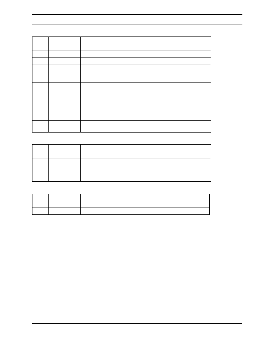
Table A.2 FT Smart Transceiver PCB Layout
Table A.3 FT Smart Transceiver Programming
Table A.4 FT Smart Transceiver Power Supply - General
Item
Check When
Completed
Description
10
Star ground configuration used.
11
Keepout areas observed for PCB.
12
Ground planes or wide traces used to lower inductance of the ground system.
13
The leakage capacitance from high frequency circuit traces is controlled via
guard traces.
14
The product's package is designed to minimize the possibility of ESD hits
arcing into the device's circuit board. If the product's package is plastic, then
the PCB is supported in the package so that unprotected circuitry on the PCB
is not adjacent to any seams in the package. The PCB is not touching the
plastic enclosure near a seam.
15
Explicit clamping of user-accessible circuitry is used to shunt ESD currents
from that circuitry to the center of the star ground on the PCB.
16
The network connector, diodes and MOV shown in Figure 4.1 are all located
close to the center of the star ground.
Item
Check When
Completed
Description
17
TP/FT-10 is used as the channel definition in the development tool.
18
If using LonBuilder 3.0.1 or NodeBuilder 1.5 and running at a clock speed
greater than 10MHz, use the latest available service pack for the development
tool. Consult the readme.txt file for further programming considerations.
Item
Check When
Completed
Description
19
Supply provides 4.75VDC minimum, 5.25VDC maximum.