Infrared input – Echelon FT 3150 Smart Transceiver User Manual
Page 79
FT 3120 / FT 3150 Smart Transceiver Data Book
73
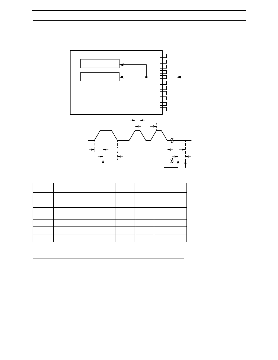
Timer/Counter Input Objects
The resolution and range of the timer/counter period options are shown in Table 3.6 in section , Notes. This object is
useful for analyzing an arbitrarily-spaced stream of input edges (or pulses), such as the output of a UPC bar-code
reader or infrared receiver.
Note: T/C clk represents the period of the clock used during the declaration of the I/O object.
Figure 3.37 Edgelog Input Object
Infrared Input
The infrared input object is used to capture a stream of data generated by a class of infrared remote control devices
(see Figure 3.38). The input to the object is the demodulated series of bits from infrared receiver circuitry. The period
of the on/off cycle determines the data bit value, a shorter cycle indicating a one, and a longer cycle indicating a zero.
The actual threshold for the on/off determination is set at the time of the call of the function. The measurements are
made between the negative edges of the input bits unless the invert keyword is used in the I/O declaration.
Symbol
Description
Min
Typ
Max
t
setup
Input data setup
0
—
—
t
win
Input pulse width
1 T/C clk —
65,534 T/C clks
t
hold
io_in() call to data input edge for
inclusion of that pulse
26.4 µs
—
—
t
wtcp
Two consecutive pulse widths
104 µs
—
—
t
oret
Return on overflow
—
42.6 µs
—
t
ret
Return on count termination
—
49.6 µs
—
Timer/Counter 1
Timer/Counter 2
IO10
IO9
IO8
IO0
IO1
IO2
IO3
IO4
IO5
IO6
IO7
Input
Bit Stream
END
OF io_in()
OVERFLOW
TIME
t
oret
t
hold
INPUT
(IO4)
t
win
t
wtcp
t
ret
t
setup
START OF
io_in()