Ontime input – Echelon FT 3150 Smart Transceiver User Manual
Page 80
Chapter 3 - Input/Output Interfaces
74
FT 3120 / FT 3150 Smart Transceiver Data Book
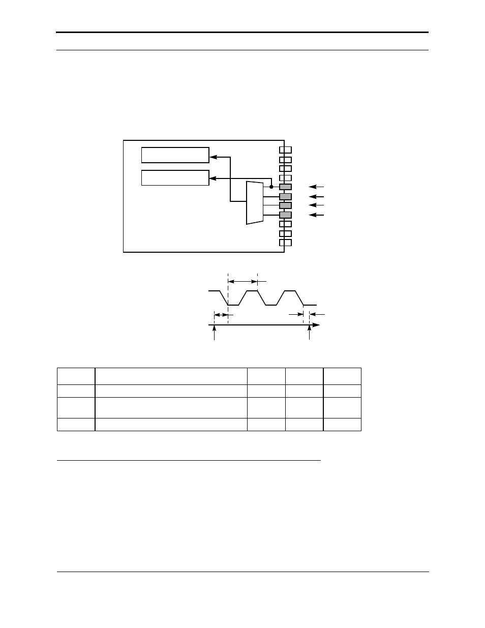
The infrared input object, based on the input data stream, generates a buffer containing the values of the bits received.
The resolution and range of the timer/counter period options is shown in Table 3.6 in section , Notes, at the end of this
chapter.
This function can be used with an off-the-shelf IR demodulator such as an NEC µPD1913 or Sharp GP1U50X to
quickly develop an infrared interface to the FT Smart Transceiver. The edgelog input object can also be used
for this purpose. However, this requires more code.
Note: max-period is the timeout period passed to the function at the time of the call.
Figure 3.38 Infrared Input Object
Ontime Input
A timer/counter may be configured to measure the time for which its input is asserted. Table 3.6 shows the resolution
and maximum times for different I/O clock selections. Assertion may be defined as either logic high or logic low.
This object may be used as a simple analog-to-digital converter with a voltage-to-time circuit, or for measuring
velocity by timing motion past a position sensor. See Figures 3.35 and 3.39.
Symbol
Description
Min
Typ
Max
t
fin
Function call to start of input sampling
—
82.2 µs
—
t
ret
End of last valid bit to function return
max-
period
max-
period
—
t
win
Minimum input period width
—
93 µs
—
Timer/Counter 1
Timer/Counter 2
IO10
IO9
IO8
IO0
IO1
IO2
IO3
IO4
IO5
IO6
IO7
mux
Input
Data Stream
INPUT
(IO0 TO IO7)
TIME
START OF
io_in()
END OF
io_in()
t
ret
t
fin
t
win (1 BIT)