Echelon FT 3150 Smart Transceiver User Manual
Page 112
Chapter 4 - Hardware Design Considerations
106
FT 3120 / FT 3150 Smart Transceiver Data Book
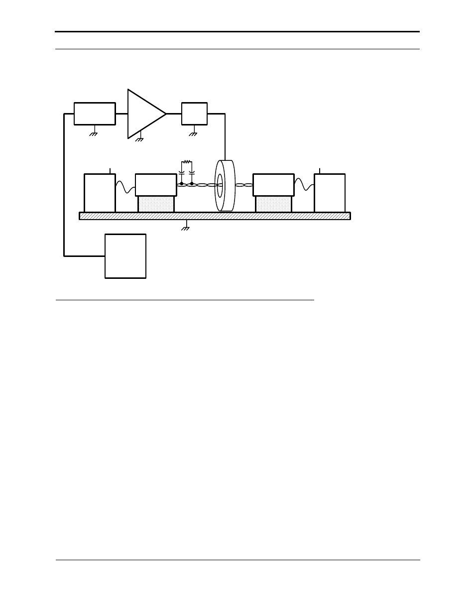
Figure 4.9 Typical EN 61000-4-6 Test Set-up for Unshielded Twisted Pair (UTP)
For the EN 61000-4-6 tests, the EUT is placed on a 10cm high, non-conducting support on top of the metal ground
plane. If the chassis of the EUT is connected to earth ground in typical installations, it should be connected directly to
the metal ground plane during the EN 61000-4-6 tests via a short wire. If the EUT is left floating in normal use, there
should be no connection between the EUT and earth ground for the EN 61000-4-6 tests. The power connections for
the AE and EUT should be routed through suitable decoupling devices, such as the non-driven M3 CDNs shown in
the figure. During the network immunity tests, any I/O lines that come out of the AE or EUT should also pass through
a decoupling network. The objective of the BCI current clamp in the figure is to drive the large common-mode noise
signal into the network cable of the EUT. The M3 CDNs in the figure ensure that the power supply inputs to the AE
and EUT are not an RF return path for the purposes of the EN 61000-4-6 test. See the EN 61000-4-6 test standard and
related articles for more information about test setups and procedures.
Termination
EQUIPMENT
UNDER
TEST (EUT)
HP8656B
SIGNAL
GENERATOR
75W
POWER
AMP
GROUND PLANE
TEST
CONTROL
COMPUTER
FCC
CDN - M3
50
Ω
AUXILIARY
EQUIPMENT
(AE)
Dressler
Alpha 250 / 75W
-6dB
75W
PAD
EMCO
ATT 6 / 75
FCC
CDN - M3
EUT
POWER
AE
POWER
GPIB
50
Ω
FCC BCI - Fischer Custom Communications
Bulk Current Injection Probe P/N F-120-9A
FCC CDN M3 - Fischer Custom Communications
Coupling De-Coupling Network P/N FCC-801-M3-16A
UTP
FCC
BCI