Introduction, Device checklist, Introduction device checklist – Echelon FT 3150 Smart Transceiver User Manual
Page 126
Appendix A - FT Smart Transceiver Design Checklist
120
FT 3120 / FT 3150 Smart Transceiver Data Book
Introduction
This appendix includes a checklist to ensure that FT Smart Transceivers-based devices meet all the specifications
presented in this user guide.
Device Checklist
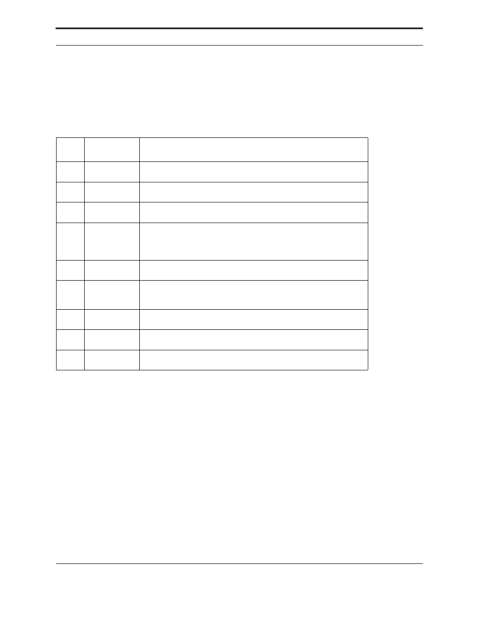
Table A.1 FT Smart Transceiver Connections
Item
Check When
Completed
Description
1
FT-X1 transformer pins connected as shown in the FT 3120 / FT 3150 Smart
Transceiver Datasheet and in Figure 4.1.
2
Environmental and electrical specifications as shown in the FT 3120 / FT
3150 Smart Transceiver Datasheet.
3
For FT-X1 designs, ESD protection diodes are connected to pins 5 and 6 of
the FT-X1 transformers.
4
Pin T2 from the FT Smart Transceiver is connected to pin 4 on the FT-X1
transformer. For FT-X2 designs, the layout connection is not routed under-
neath the old pin traces (pins 3 and 4) of FT-X1 (see “FT 3150 Evaluation
Board Composite Top Layer” on page 145).
5
The recommended number and placement of 0.1µF bypass capacitors are
near the FT Smart Transceiver.
6
The FT Smart Transceiver input clock frequency is 5MHz, 10MHz, 20MHz,
or 40MHz and accurate to ± 200 ppm. The input clock frequency of 40MHz is
valid for the FT 3120 Smart Transceiver only.
7
The FT Smart Transceiver and FT-X1 or FT-X2 Communications Transformer
are placed adjacent to one another on the same printed circuit board.
8
If required, a low voltage interrupt (LVI) circuit with open collector output is
used to supply a reset signal to the FT Smart Transceiver.
9
Clamping diodes and 470V MOV are used in the ESD protection circuit
shown in Figure 4.1.