Neurowire slave mode – Echelon FT 3150 Smart Transceiver User Manual
Page 70
Chapter 3 - Input/Output Interfaces
64
FT 3120 / FT 3150 Smart Transceiver Data Book
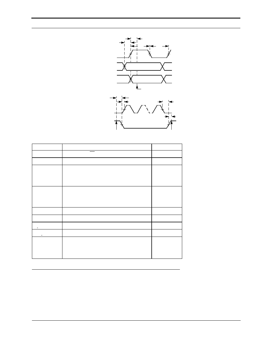
Figure 3.29 Neurowire (SPI) Master Timing
Neurowire Slave Mode
In Neurowire slave mode, pin IO8 is the clock (driven by the external master), IO9 is the serial data output, and IO10
is the serial data input. Serial data is clocked out on pin IO9 at the same time as data is clocked in from pin IO10. Data
is clocked by the rising edge of the clock signal (default), which may be up to 18kbps at 10MHz. This data rate scales
with FT Smart Transceiver input clock rate, for example: 72kbps at 40MHz. The clockedge(-) keyword changes
Parameter
Description
Typ
t
fin
Function call to CS active
69.9 µs
t
ret
Return from function
7.2 µs
t
hold
Active clock edge to sampling of input data
20 kbps bit rate
10 kbps bit rate
1 kbps bit rate
11.4 µs
53.4 µs
960.6 µs
t
high
Period, clock high (active clock edge = 1)
20 kbps bit rate
10 kbps bit rate
1 kbps bit rate
25.8 µs
67.8 µs
975.0 µs
t
low
Period, clock low (active clock edge = 1)
33.0 µs
t
setup
Data output stable to active clock edge
5.4 µs
t
cs clock
Select active to first active clock edge
91.2 µs
t
clock cs
Last clock transition to select inactive
81.6 µs
f
Clock frequency = 1/(t
high
+ t
low
)
20 kbps bit rate
10 kbps bit rate
1 kbps bit rate
17.0 kHz
9.92 kHz
992 Hz
DATA OUT
DATA IN
CLOCK
SELECT
CLOCK
END OF
io_in() OR io_out()
START OF
io_in() OR io_out()
t
cs_clock
t
clock_cs
t
fin
t
ret
t
low
t
high
t
hold
t
setup
INPUT SAMPLED