Build the t ail surf a ces, Build the horizontal stabiliz er, Get read y to b uild – Top Flite TOPA0300 User Manual
Page 9
1. Unroll the plan sheets
. Re-roll the plans
inside-out to mak
e them lie flat.
2. Remo
v
e
all par
ts from the bo
x. As y
ou do
, fig-
ure out the name of each par
t b
y
compar
ing it
with the plans and the par
ts list included with this
kit. Using a f
elt tip or ball point pen, lightly wr
ite
the par
t
name
or
siz
e
on each piece to a
v
oid
confusion later
. Use the die-cut patter
ns sho
wn
on pages 7 and 8 to identify the die-cut par
ts and
mar
k them
bef
ore
remo
ving them from the
sheet. Sa
v
e
all scr
aps
. If an
y of the die-cut par
ts
are difficult to punch out, do not f
orce them!
Instead, cut around the par
ts with a hob
b
y
knif
e
.
After punching out the die-cut par
ts
, use y
our T
-
Bar or sanding b
loc
k to
lightl
y
sand the edges to
remo
v
e
an
y die-cutting irregular
ities
.
3. As y
ou identify and mar
k the par
ts
, separ
ate
them into g
roups
, such as
fuse
(fuselage),
wing
,
fin
,
stab
(stabiliz
er), and
har
d
ware
.
1. W
o
rk
on a flat surf
ace o
v
er the plans co
v
e
red
with w
a
x
ed paper
. Ref
er to the plans to identify
the par
ts and their locations
.
The plans ma
y be
cut apar
t if space is a prob
lem.
2. Punch out both sets of the die-cut 3/32” balsa
ribs
S-1
through
S-7
. There is a jig tab on the
bottom edge of each of these r
ibs
. If an
y of
these break off
, carefully glue them bac
k on with
a drop of thin CA. Lightly sand an
y imperf
ec-
tions
. Y
ou ma
y need to finish cutting the notch in
the f
orw
ard por
tion of
S-1
for the
Stab Joiner
(SJ
) with a knif
e
. Use a pen to mar
k
the e
xten-
sions of the bottom edge of the r
ibs across the
fore and aft ends of the jig tabs
. These mar
ks
will help when y
ou tr
im off the jig tabs later
.
3. The stab
T
railing Edg
es
(S
) are die-cut from
1/4” balsa. Since some cr
ushing ma
y occur dur-
ing die-cutting w
ood of this thic
kness
, the
y
are
supplied slightly long and can be tr
immed. T
rue
up all edges of these pieces with a T
-bar
.
❏❏
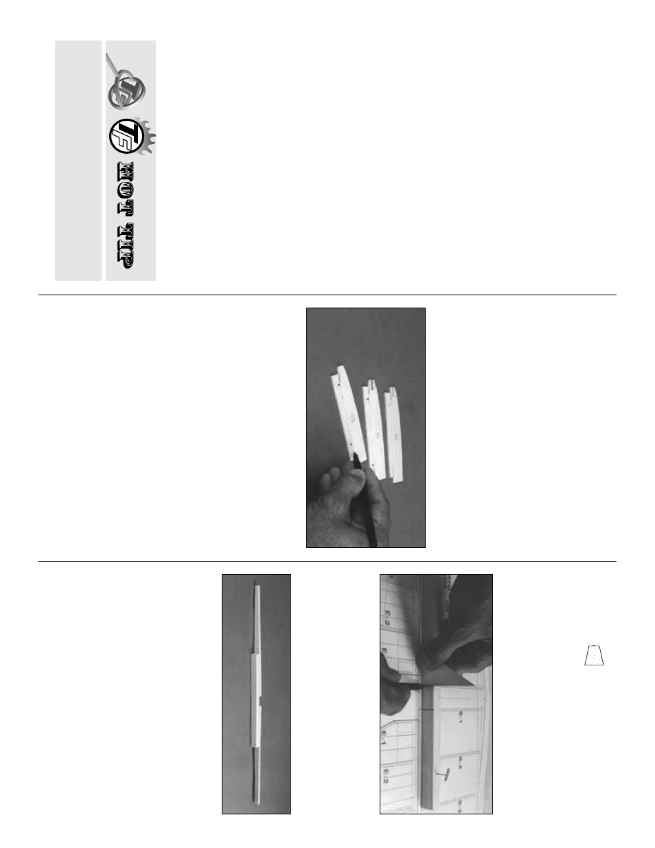
4. Cut the stab
Leading Edg
es
(LE
’s) to
length from the 1/4” x 15” tapered balsa stoc
k.
The
y
should be about 1/4” longer than the length
sho
wn on the plans f
or the stab LE.
❏❏
5. Center the 1/2” x 5/8” x 9-3/4” balsa
TE
Center Brace
o
v
er the plans and pin it in place
.
Use a tr
iangle and pen to mar
k
the inboard ends
of the Stab TE. Remo
v
e
the TE Center Br
ace
from the b
uilding board.
❏❏
6. Apply thic
k CA to one half of the TE
Center Br
ace
, then align the inboard end of a
Stab TE
with the ref
erence line y
ou just dre
w
.
Glue the TE Center Br
ace in position.
The TE
Center Brace m
ust be centered on the Stab
TE.
Repeat this oper
ation f
o
r the other half of
the TE, then use long T
-pins to pin the assemb
ly
o
v
er the plans
.
NO
TE: P
osition the outboar
d ends of the
TE about 1/2
”
abo
ve the boar
d
. The TE
Center Brace should be raised about 3/8
”
.
(See ne
xt photo.)
FIN / STAB LE
Build the horizontal stabiliz
er
B
UILD THE T
AIL SURF
A
CES
Zipper-top f
ood stor
age bags are a handy
w
a
y to store y
our small par
ts as y
ou sor
t, iden-
tify
, and separ
ate them into sub-assemb
lies
.
Get read
y to b
uild
9