Top Flite TOPA0300 User Manual
Page 30
When e
v
er
ything is loc
k
ed in place
, glue the
assemb
ly together
. The 3/16” side str
ingers ma
y
no
w be tr
immed flush with the f
o
rw
ard edge
of F-1.
❏
12. Lightly sand the outside of the tw
o 36”
outer pushrod tubes then inser
t them through
the holes in F-2 through F-8. T
rim the tubes so
that 1/4” protr
udes past F-2 and F-8. Apply a
drop of medium CA to the pushrod tubes at each
fo
rm
er
e
xcept F-2
.
❏
13. Use 30-Min
ute Epo
xy to glue the 1/4”
birch ply
Landing Gear Plate
betw
een f
o
rm
er
LF and F-3. Be sure that the notches fit w
ell and
that the Landing Gear Plate is fir
mly against the
K
eel.
While the epo
xy cures there are a f
e
w
other par
ts w
e
can w
o
rk
on.
❏
14. Cut tw
o 3/16" str
ingers from the 24"
lengths pro
vided, to
fit fr
om F-2 to F-4 in the
fir
st set of notc
hes abo
ve the Main String
e
r.
Glue them in place
, then sand the ends flush
with the f
o
rmers
.
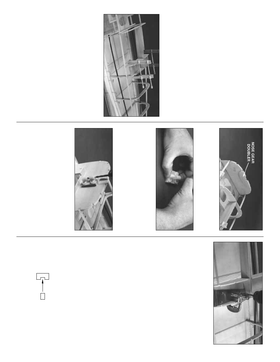
❏
15. Glue the 1/8” die-cut ply
Nose Gear
Doub
ler
to the aft side of F-1. Be sure to align
the str
inger notches
.
❏
16. Center the n
ylon
Nose Gear Bearing
on
the tapered 1-1/4” x 1-5/8” bass
w
ood
Nose
Gear Bloc
k
. Mar
k the mounting holes in the
Nose Gear Bloc
k, then dr
ill the holes with a 1/8”
bit. Dr
ill the f
our
inde
x marks
on the f
orw
ard
side of F-1 with a 5/32” bit.
❏
17. Install the Nose Gear Bear
ing/Bloc
k
on
F-1 with f
our 4-40 x 1” P
an Head Bolts and f
our
4-40 Blind Nuts
. The wide end of the Nose Gear
Bloc
k points
a
w
a
y
fr
om the b
uilding boar
d
.
Dr
ill out the
Nose Gear Wire Hole with a 1
3/64”
dr
ill bit. Remo
v
e
the Nose Gear Bear
ing/Bloc
k
then use thic
k CA to mount the bass
w
ood b
loc
k
per
manently to F-1. Be sure that all of the
mounting holes sta
y in alignment.
❏
18. After the epo
xy on the 1/4” Landing Gear
Plate has fully cured (
an hour or more
)
c
lamp
both of the bent alumin
um
Main Landing Gear
str
uts in position. The str
uts should touch the
K
eel and F-3. Use a
9/64”
dr
ill bit to dr
ill through
the mounting holes in the str
uts and also
through the Landing Gear Plate
. Enlarge the
holes in
onl
y
the
pl
yw
ood
Landing Gear Plate
with an 11/64” (or 3/16”) dr
ill bit to pro
vide
clear
ance f
or the 8-32 mounting bolts
.
❏
19. Use an
8-32 T
ap to cut threads
in the
alumin
um Main Landing Gear mounting holes as
w
ell as the axle mounting holes
. T
empor
ar
ily
install the Landing Gear in the fuse with six
8-32
x 1/2”
soc
k
et head cap scre
ws
.
❏
20.
IMPOR
T
ANT
: Bef
ore y
ou do this step,
make cer
tain that the Main String
er
s are
pinned or weighted FLA
T onto the b
uilding
surface
.
Cut and install all the remaining 3/16”
square str
ingers f
or the fuse bottom. Chec
k each
fo
rmer f
or twists and the correct angle bef
ore
y
ou use glue
. Use the F
o
rm
er Angle T
e
mplate
as y
ou proceed. The inside ends of the center
str
inger should be sanded f
or a flush fit, then
b
utt glued to the ends of the K
eel.
❏
21. Glue tw
o of the f
our 1/8” x 3/16” x 24”
Main Sub-String
er
s
into the g
roo
v
e
in one of
MAIN
SUB-STRINGER
STRINGER
MAIN
30