Install engine and tank – Top Flite TOPA0300 User Manual
Page 36
its correct length, then inser
t it from the ser
v
o
location through F-1 into the Connector on the
Nose Wheel Steer
ing Ar
m. Clip the Metal Cle
vis
onto the ser
v
o
hor
n. Align the ser
v
o
hor
n and
Nose Wheel Steer
ing Ar
m as sho
wn on the
plans
. Secure the Pushrod in the Quic
k
Connector with a 4-40 x 1/4” Soc
k
et Head
Cap Scre
w
.
❏
6. When the Nose Wheel Steer
ing Ar
m is
adjusted, remo
v
e
the Nose Gear Wire
. File a flat
spot where the steer
ing ar
m loc
king scre
w
contacts the wire so the steer
ing ar
m can be
loc
k
ed in position.
Depending on y
our choice of engine
, 2-strok
e
or
4-strok
e
, y
ou ma
y ha
v
e
to be a little in
v
entiv
e f
o
r
throttle
, tank and m
uffler hookup
. The installation
of a 2-strok
e .60 to .90 siz
e
engine is pretty
str
aightf
orw
ard. Use the ser
v
o
locations
pro
vided on the Ser
v
o
T
ra
y, mount the tank
side
w
a
ys as sho
wn, and use a T
op Flite In-Co
wl
Muffler (T
OPQ7916). Some 4-strok
e engines
allo
w the throttle linkage to be rotated 180
deg
rees
, thereb
y per
mitting the same ser
v
o
setup as a 2-strok
e engine
.
The O
. S
. .91
Sur
pass is one such engine
.
This model flies v
e
ry
w
ell on an O
. S
. .61 SF
2-strok
e engine
. As the .61SF also allo
ws f
or the
most “ster
ile” setup with e
v
er
ything contained in
the co
wl, w
e
will detail its installation.
We
h
a
ve
also included instr
uctions f
or those who pref
er to
use one of the larger 4-strok
e engines
.
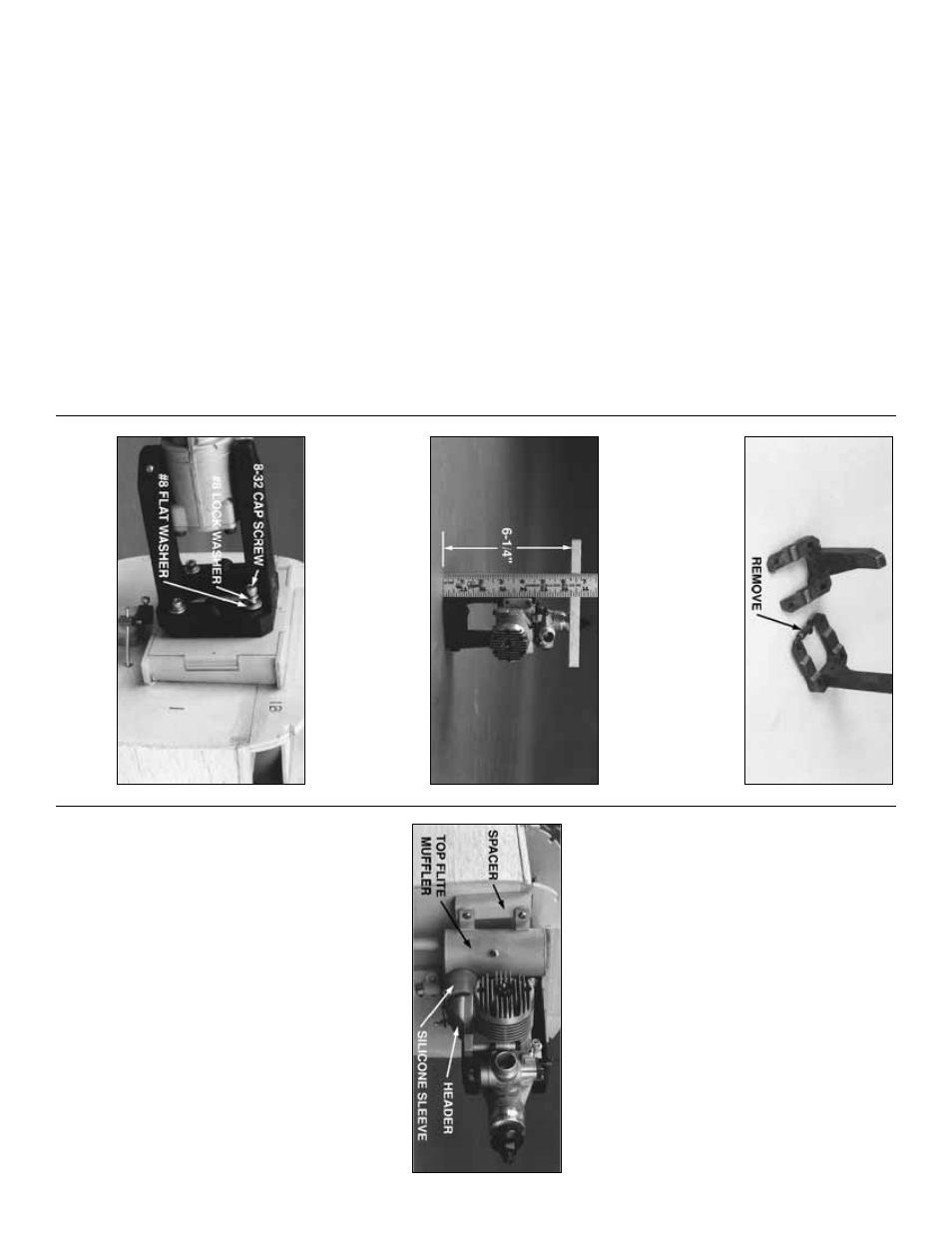
❏
1. Remo
v
e the spacer bar from the bac
k of
both Engine Mount halv
es and tr
im off an
y b
urrs
.
Snap the Engine Mount halv
es together and
place the engine of y
our choice betw
een the r
ails
,
adjusting the width betw
een the r
ails accordingly
.
❏
2. P
osition the engine so that the propeller
bac
kplate is e
x
actly 6-1/4” (159 mm) from the aft
edge of the Engine Mount. Mar
k, dr
ill and tap
the engine mounting holes to accept the 8-32
soc
k
et head cap scre
ws included with this kit.
❏
3. Install the Engine Mount on the Fire
w
all as
sho
wn with f
our 8-32 x 1-1/4” Soc
k
et Head Cap
Scre
ws
, #8 Flat W
ashers and #8 Loc
k W
ashers
.
Use the inde
x
mar
ks on the Fire
w
all to center
the Engine Mount.
NO
TE: W
e
str
ongl
y recommend that ALL
engines be mounted horizontall
y
to pr
o
v
ide
enough cooling airflo
w o
ver the c
ylinder
via the normal co
wl air inlets.
❏
4. Bolt the engine to the mount.
If using the optional T
op Flite In-Co
wl Muffler
and Header
, perf
orm the f
ollo
wing step:
❏
5
.
Bolt the T
op Flite Header (not included) to
the engine
. Use the Silicone Slee
v
e
to attach the
T
op Flite In-Co
wl Muffler (not included) to the
Header
. Mak
e a spacer b
loc
k f
or the m
uffler from
scr
ap
.
NO
TE:
Do
not
use balsa. Use epo
xy to
glue the spacer b
loc
k to F-1 in line with the
m
uffler mounting lugs
. Shor
ten the m
u
ffler or
header connection tubes if required, so that the
m
u
ffler can be scre
w
ed to the spacer using the
supplied scre
ws and silicone w
ashers
.
❏
6. Dr
ill a 3/16” hole through the Fire
w
all in line
with the ser
v
o
and throttle ar
m on the engine
.
K
eep the hole c
lose to the le
vel of the ser
v
o
tra
y
so that the pushrod will be ab
le to pass
under the Fuel T
ank.
Install engine and tank
36