A=a a a, Attac h the stab and fin – Top Flite TOPA0300 User Manual
Page 37
NO
TE: Due to the v
ariety of hook-up methods
pref
erred b
y
diff
erent modeler
s, we do not
pr
o
vide an
y thr
ottle linka
g
e
har
d
ware in most
of our kits. Ho
we
ver
, we do off
er the f
ollo
wing
method as one that w
orks well. Y
ou pr
obab
ly
ha
ve the materials b
uried some
where under
y
our w
o
rkbenc
h.
❏
7. Inser
t a shor
t length of outer pushrod tube
through the throttle hole in the Fire
w
all. Attach a
Ball Link to the throttle ar
m on the engine
. Scre
w
a Ball Link Soc
k
et onto a 2-56 x 12” threaded
wire pushrod. Inser
t the pushrod through the
outer pushrod tube
, then attach the Ball Link and
Soc
k
et. Bend a “dog leg” in the pushrod near the
ser
v
o so that the wire will be just abo
v
e
the
ser
v
o
hor
n. Attach the pushrod wire to the ser
v
o
with a small pushrod Connector
. Connect the
ser
v
o
to y
our r
adio and adjust the pushrod
length and position on the ser
v
o
hor
n to obtain
full throttle mo
v
ement.
❏
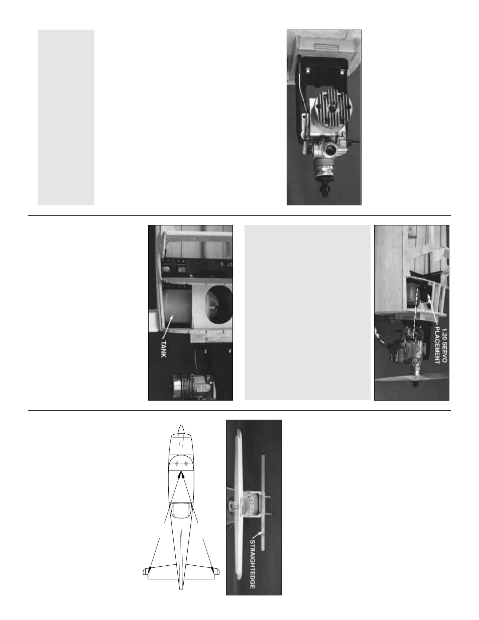
8. Assemb
le a
12 oz. Great Planes Fuel
T
ank
(GPMQ4105) with the
right angled
fuel
pic
kup tube
. The T
ank is installed “
side
w
a
ys
”
under the Instr
ument P
anel with the bac
k end
pointing to
w
ard the r
ight side of the fuse
. W
o
rk
a
small piece of 1/4” f
oam r
u
b
ber abo
v
e
and belo
w
the T
ank, then slide a couple of scr
ap balsa
stic
ks under the tank to secure it in position and
pro
vide throttle pushrod clear
ance
. W
e
fle
w all of
our test flights with the tank mounted in this
position and e
xper
ienced no prob
lems
.
❏
9
.
Mar
k and dr
ill 1/4” fuel tube holes through
the fire
w
all, being careful not to damage the tank.
Install both the fuel supply and pressure tubes
.
F
or ease of fueling w
e
suggest a
Great Planes
Fuel Filler V
alve
(GPMQ4160) that can be
mounted on the co
wling dur
ing final assemb
ly
.
❏
1. Chec
k the fit of the Stab with the Stab
Saddle
. Mak
e an
y adjustments to the Stab
Saddle v
e
ry
carefully
, so that y
ou
don’t c
hang
e
the b
u
ilt-in incidence angle
.
❏
2. Put the stab on the saddle and add a small
w
eight to hold it in place
. Place a 36”
str
aightedge across the Wing Saddle and clip it
to F-2B
. Sight across the top of the Stab to the
str
aightedge from six to ten f
eet behind the
model. If both Stab tips are not equidistant
belo
w the str
aightedge
, mak
e
small
adjustments
to the Stab Saddle to correct the prob
lem. Use a
str
ing, pinned to the top center of F-2, to
equaliz
e the distance of the Stab tips
.
A=A
A
A
Attac
h the stab and fin
Use scr
ap 3/16” or 1/4” plyw
ood to mak
e
tw
o
ser
v
o
mounting b
loc
ks appro
ximately 3/4”
square
. Use epo
xy to glue these b
loc
ks as
sho
wn abo
v
e
the Fuel T
ank Roof so that the
ser
v
o
hor
n aligns with the throttle ar
m on the
engine
. Use the same pushrod technique as
descr
ibed in Step 8 f
or a direct hookup
. The
do
wn-side to this method is that the ser
v
o
will
not be accessib
le after sheeting without cutting
into the top of the fuse
...b
ut, because ser
v
o
s
are gener
ally quite reliab
le
, this ma
y ne
v
er
be necessar
y.
SER
V
O
OPTION FOR 1.20 ENGINE
T
o
simplify the throttle hookup f
or a 1.20 4-
strok
e
engine y
ou ma
y w
ant to consider the
follo
wing suggestion.
37