Hinge the contr ol surf a ces – Top Flite TOPA0300 User Manual
Page 42
one end attached to a pin centered at the tail)
out to a wing tip
. Put a piece of tape on the
str
ing to mar
k the intersection of the str
ing and
the wing tip
. Swing the str
ing o
v
er to the other
wing tip and chec
k to see if the distances are the
same (see diag
ram). Adjust the position of the
tr
ailing edge of the wing until the wing is
proper
ly aligned.
NO
TE: Make sure the wing is held securel
y
and cannot shift while y
ou are drilling the
mounting holes.
❏
3.
Lightl
y
mar
k the center of the wing mount
holes on the Mounting Bloc
ks
, with a
1/4” drill
bit
inser
ted through the Bolt Plates in the wing.
Do
not
dr
ill through the Mounting Bloc
ks with
the 1/4" Bit.
❏
4.
Remo
ve the wing
and dr
ill the holes with a
#10
(or 13/64”) dr
ill bit through the wing mount
b
loc
ks
. K
eep the dr
ill as v
e
rtical as possib
le
. T
a
p
the holes with a
1/4-20 tap
. Add a couple drops of
thin CA to the holes to harden the threads
, then
re-tap the holes after the CA has fully cured.
❏
5. Bolt the wing in position with
1/4-20 x 2”
n
ylon
Wing Bolts
.
The n
ylon Wing Bolts ma
y be
shor
tened to 1-1/2” if desired.
NO
TE: Hinging is usuall
y done after
co
vering and painting; ho
we
ver
, because
the contr
ol linka
g
es will be enc
losed in the
fuse
, y
ou should temporaril
y install the
hing
es WITHOUT using CA so that the
c
le
v
ises can be adjusted. The hing
e
locations are sho
wn on the plans.
❏
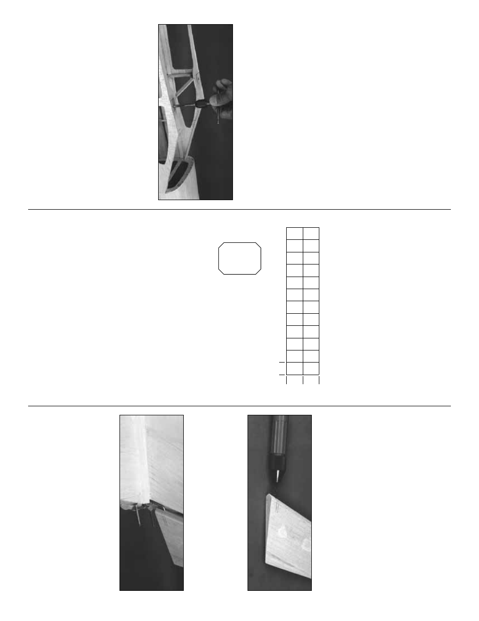
Cut 15 hinges (3/4” x 1”)
from the 2” x 9” CA hinge
str
ip
. T
rim the cor
ners at a
45 deg
ree angle to mak
e
inser
tion easier
.
❏
1. Use a
#11 b
lade
in a hob
b
y
knif
e to cut
matching hinge slots in the Stab and the
Ele
v
ators at the locations sho
wn on the plans
.
T
est fit the Ele
v
a
tors to the Stabiliz
er with all
hinges
and
the wire joiner in place
. Mak
e sure
both Ele
v
ators are set at the same angle
. Mak
e
adjustments to the joiner wire and pushrod
length if necessar
y.
Do steps 2 and 3 AFTER the model has been
co
vered.
❏
2. Chamf
er the ends of the joiner wire slightly
with a file
. Roughen the “ar
m
s” with coarse
sandpaper
. Clean the “ar
ms” thoroughly with
ru
b
bing alcohol. W
o
rk
a generous amount of
30-Min
ute Epo
xy into the wire joiner holes in
the ele
v
ators
.
❏
3. W
o
rk
the ele
v
ator hinges into the stab and,
as y
ou do this
, inser
t the wire joiner all the w
a
y
into the ele
v
ator holes
. Wipe a
w
a
y
an
y e
xcess
epo
xy
. Glue the hinges in place using 4-6 drops
of
thin
CA on
both sides of eac
h hing
e
.
❏
1. Hold the Rudder against the Fin. Mar
k
the
location of the T
orque Rod
tiller
on the LE of the
Rudder
. Dr
ill a 9/64” hole into the Rudder LE
that is in line with the T
orque Rod
tiller
. A hand-
tur
ned
Pin Vice
is a good tool f
or this pur
pose
.
❏
2. Cut a 9/64”-wide g
roo
v
e
from the bottom of
the Rudder to the tiller hole
. Ream out the
g
roo
v
e
with a 9/64” dr
ill bit or round file
. Inser
t
the T
orque Rod tiller into the hole
, then seat the
Rudder against the Fin TE. Mak
e whate
v
e
r
adjustments are necessar
y to align the Rudder
in the neutr
al position. Doub
le chec
k that the
ser
v
o is centered.
Hing
e the rud
der and ailer
ons
Hing
e the ele
v
ator
1"
1"
3/4"
HINGE THE CONTR
OL
SURF
A
CES
42