Top Flite TOPA0300 User Manual
Page 29
❏
4. P
osition (without glue)
F-1
through
F-9
ov
e
r
the plans and Main Str
inger
.
Are y
our 3/16”
pushrod holes dr
illed?
IMPOR
T
ANT NO
TE: Cut the “Former Angle”
T
emplate fr
om the plans and glue it to stiff
car
dstoc
k or scrap w
ood. T
rim and sand it
to siz
e
. Hold it on the AFT side of all
former
s to position them at the correct
angle while gluing. An
y small warps or
twists will be taken out when the 3/16”
string
er
s are glued in later
.
❏
5. Using the F
o
rm
er Angle template
, star
t
gluing the
former
s
to the Main Str
ingers star
ting
with F-3,
w
orking to
war
d
s the rear
. Don’t glue
F-1 or F-2 y
et.
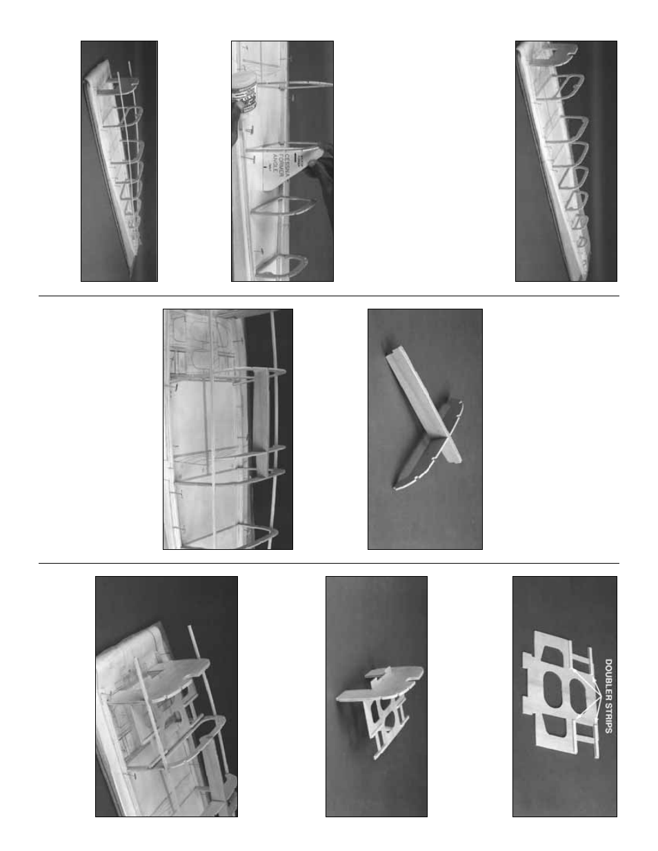
❏
6. Inser
t (
without gluing
) tw
o 3/16” x 3/16” x
48”
string
er
s
into the lo
w
est notches on both
sides
, that r
un from F-1 to F-9 as sho
wn in the
photog
raph. Star
ting at F-9,
c
hec
k the f
o
rmer
angle once a
gain with the Former Angle
template
. Mak
e sure that y
ou str
aighten out an
y
twists
, then glue the str
ingers to F-9 with thin
CA. Contin
ue f
o
rw
ard,
c
hec
king and aligning
each f
o
rmer bef
ore reaching f
o
r the CA.
F-3 is
the last f
o
rmer y
ou need to glue to the
string
er
s at this time
.
❏
7. Inser
t and glue the 1/8” die-cut f
o
rm
er
LF
into the slot in the fuse K
eel. Mak
e
sure that it is
square and flush with the top and bottom of
the K
eel.
❏
8. Inser
t the K
eel assemb
ly into the upper
center notches of F-2 and F-3. The notches on
the tips of LF should be resting on the 3/16”
str
ingers
. Adjust F-2 so that the bottom ends are
o
v
er the dashed ref
erence lines on the plan and
the f
orw
ard edge of the K
eel is flush with the aft
side of F-2. Glue F-2, the K
eel and LF at all
points of contact.
❏
9. Glue the tw
o halv
es of the die-cut 1/8” ply
Ser
v
o
T
ra
y
together
. Cut f
our 1/8” x 1/4” x 2-1/4”
doub
ler str
ips from scr
ap ply left o
v
er from die-
cut sheets
. Glue these doub
lers on both ends of
the ser
v
o
holes f
or reinf
orcement.
❏
10. Carefully lift F-1 out of the fr
ame
.
Yo
u
didn’t glue it in, did y
ou?
Inser
t the f
orw
ard end
of the Ser
v
o T
ra
y
into the Fire
w
all opening in F-
1. The ser
v
o
reinf
orcement str
ips should f
ace
aw
ay
from the b
uilding board.
❏
11. Fit F-1 and the Ser
v
o T
ra
y
bac
k into the
fuse fr
ame
. W
o
rk
the aft end of the Ser
v
o
T
ra
y
into the notch in F-2. Align F-1 o
v
er the plan.
29