Top Flite TOPA0300 User Manual
Page 33
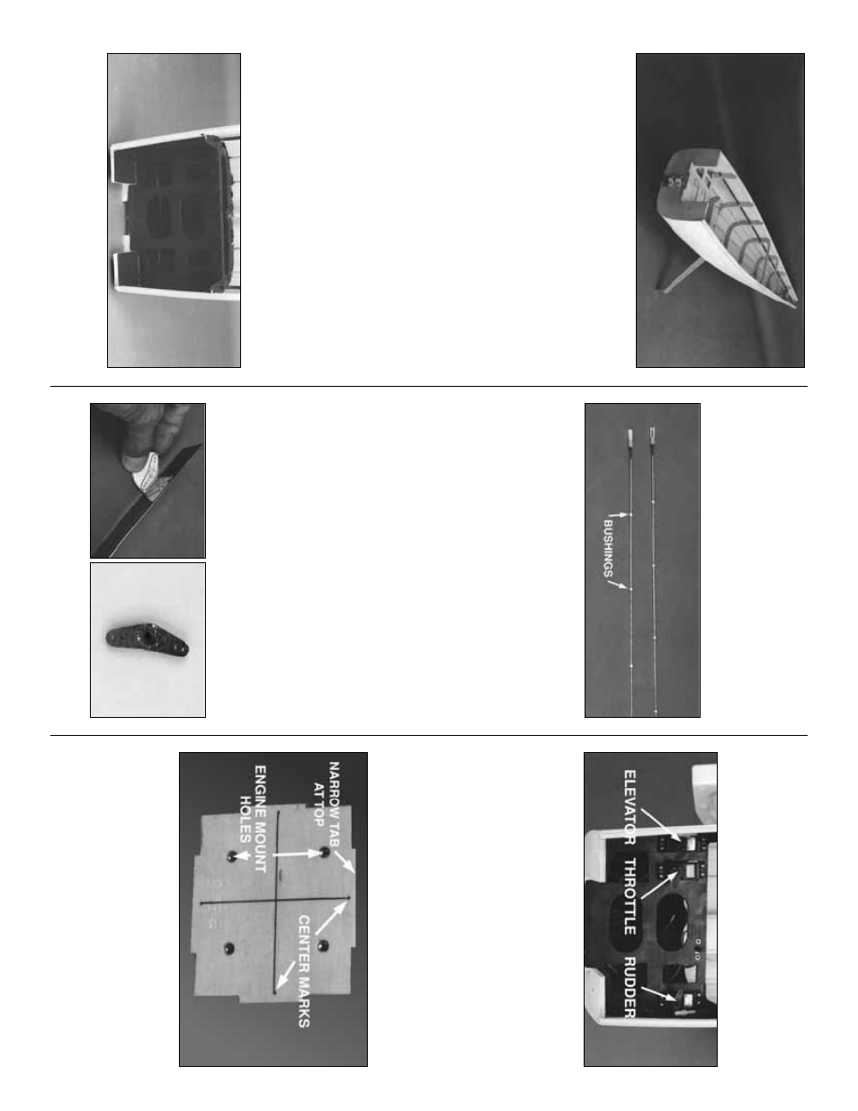
Remo
v
e
the hull (I meant to sa
y fuselage) from
the b
u
ilding board, and install the landing gear
with six 8-32 x 1/2” soc
k
et head cap scre
ws
. The
landing gear str
uts pro
vide a b
u
ilt-in stand to
help a
v
oid hangar r
ash on the underside
. Looks
pretty sleek, huh?
SPECIAL B
UILDER’S NO
TE:
As this model has
been designed with the scale b
uilder in mind,
the ser
v
o
s
, receiv
er
, batter
y
and tank are all
hidden under the instr
ument panel so the
y are
less conspicuous and lea
v
e
the cabin inter
ior
open f
or unlimited detailing. Because of this
location y
ou will find it m
uch easier to install
these components bef
ore the top of the fuse is
assemb
led. W
e
are not sa
ying that the
y can’t be
installed (or remo
v
ed) later
, it’
s just
m
uch easier
to do it no
w
.
❏
Bef
ore assemb
ling the fuse top
, fuel proof and
paint the inter
ior from F-1 to F-2 including the
ser
vo
tr
a
y. W
e
used K & B Blac
k Super P
o
xy paint
with satin catalyst to do both jobs at one time
.
❏
1. Locate the tw
o .074” x 36”
Pushr
od Wires
.
Cut six or se
v
en 1/4” long b
ushings of inner
pushrod tube
, then slide these along the wire
from the unthreaded end. Space them out e
v
enly
b
ut mak
e sure that the b
ushings on the ends are
at least 4” from the end of the wire
. If the
b
ushings slide too easily
, use a small drop of thin
CA to hold them in position. Slide a silicone
Retainer
onto the rear of a n
ylon
Cle
vis
, then
scre
w the Cle
vis onto the Pushrod about 14
tur
ns
. Mak
e a second Pushrod in the same
manner
.
❏
2. Mak
e
sure that the CA on the b
ushings has
thor
oughl
y cured
(y
ou don’t w
ant the Pushrods
glued to the inside of the tubes
) then inser
t the
Pushrod wires o
v
er the top of F-1 into the
fo
rwar
d
end of the Pushrod T
ubes and slide
them all the w
a
y through.
❏
3. Cut the
Rud
der Ser
v
o
Horn pattern
from
the plans and glue it to a large ser
v
o
wheel with
ru
b
ber cement. Cut out the custom hor
n shape
with a r
a
z
or sa
w and g
rinding wheel. Dr
ill the
cle
vis holes with a 1/16” bit.
❏
4. Install three ser
v
o
s as sho
wn with their
splined shafts to
war
d
F-1.
Depending on
engine choice (2-strok
e or 4-strok
e), the throttle
ser
v
o
location can be on either the left or the
right side of the ser
v
o
tr
a
y. The receiv
er
s
witc
h
can also be installed in the ser
v
o
tr
a
y
at this
time
, or y
ou could mount it through the fuse
sheeting dur
ing final assemb
ly
.
❏
1. Dr
ill f
our 15/64” diameter holes through the
laminated Fire
w
all f
or the engine mounting bolts at
the mar
k
ed locations
. Inser
t f
our 8-32 b
lind n
u
ts
into the holes from the aft side (that’
s the side with
the lightening hole) and seat them with gentle taps
from a hammer
. Wic
k
a little thin CA around the
edge of each n
ut to secure it in position.
Frame fusela
g
e
top
Install pushr
ods and ser
v
o
s
Fuelpr
oof and paint the interior
33