Top Flite TOPA0300 User Manual
Page 44
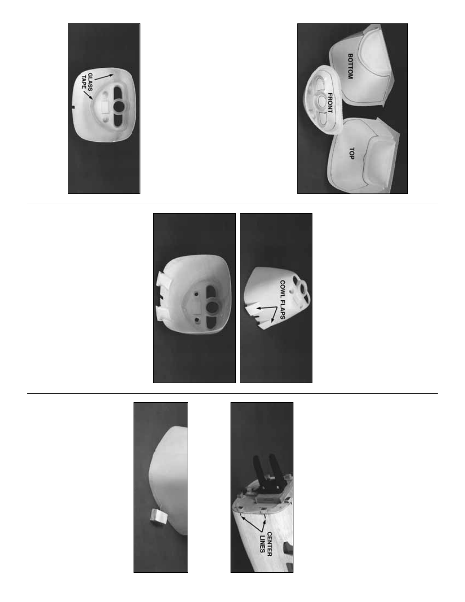
❏
1. Use a
ne
w # 11 b
lade
in a hob
b
y
knif
e to
score
around the
cutlines
inside all three par
ts
of the ABS co
wl as sho
wn in the photo
. Fle
x
the
ABS along the scores until the e
xcess mater
ial
breaks free
. Use a Moto-T
ool and cutting b
urr to
cut the air intak
es and propshaft opening.
❏
2. Use a sanding b
loc
k to clean up the edges
and to mak
e an
y adjustments that ma
y be needed
for a nice flush fit. Roughen the inside edges of the
joints with coarse sandpaper
, then fit the three
par
ts together and secure them with tape
. Carefully
wic
k thin CA around the joints and allo
w the par
ts
to cure
. Do
not
use CA acceler
ator
.
❏
3. F
or added strength, epo
xy 1”-wide
fiberglass cloth tape across all of the seams on
the inside of the co
wl.
IMPOR
T
ANT
: Hot air g
enerated b
y
the
engine MUST be vented fr
om the co
wl
or
y
our engine will o
verheat and quit!
While
w
e
e
xper
ienced no o
v
erheating prob
lems with
our
engine running slightl
y
ric
h
and both air
inlets open, y
ou ma
y pref
er
not
to open
both
air inlets
. By lea
ving only the inlet in front of
the cylinder open,more air is f
orced directly
o
v
er the cylinder and out through the co
wl
flaps
. If y
ou choose to open the second inlet, a
dumm
y cylinder head or baffle could be
installed behind the opening to restr
ict the
air-flo
w
into the co
wl.
❏
4
.
Use a hob
b
y
knif
e to cut along the
embossed lines on the inside of the co
wl f
or the
co
wl flap openings
. Use the patter
ns on the plans
to cut the co
wl flap sides from e
xcess 1/16” ply
lefto
v
er from the ser
v
o
hatch die-cut sheet. Cut
out the
co
wl flaps
from the ABS sheet, using the
cut lines f
o
r ref
erence
. Glue the co
wl flap sides to
the inside edges of the co
wl, then center the flap
across the sides and glue it in place
.
❏
5. Fill the seams on the outside of the co
wl
with
Bondo
®
type automotiv
e body filler
.
❏
1. Mount the engine
. Slide the Co
wl into
position as f
ar as it will fit. Cut a slot in the Co
wl
for the Nose Gear
. Sand the hardw
ood Co
wl
Mounting Bloc
ks and balsa Co
wl Ring until the
Co
wl fits flush with the fuse
. With the co
wl in
position, install a spinner on the prop shaft and
chec
k the clear
ance around the front of the
Co
wl. Sand the aft edge of the Co
wl until the
spinner is centered and is 1/16” a
w
a
y
from the
front of the Co
wl.
❏
2. Dr
a
w
a shor
t line to e
xtend the center
line of
each Co
wl Mounting Bloc
k onto the f
o
rw
ard
edge of the balsa sheeting.
❏
3. Sandwich a T
-pin betw
een tw
o scr
aps of
1/4” balsa to mak
e
a quic
kie height gauge
. Glue
the top to the bottom piece of balsa with CA.
Hold the height gauge and the Co
wl flat on the
w
o
rk
bench, then rotate the height gauge around
the per
imeter of the co
wl to
lightl
y
scr
ibe a line
.
NO
TE: A pen or pencil ma
y be substituted
fo
r the “Pin” so long as the point is 1/4”
abo
ve the w
ork surface
.
Fit the co
wl to the fusela
g
e
and engine
Assemb
le the co
wl
44